
Rear door heat exchanger instrumentation for heat quantity measurement

a heat exchanger and instrumentation technology, applied in the field of heat management, can solve the problems of increasing the heat load proportionally, the need for an external monitoring system to detect failures, and the inability of historically installed heating, ventilating and air conditioning systems to keep up with this growth, so as to reduce the flow of heat transport medium, increase the load level of the rack mounted computer system, and increase the air flow

Inactive Publication Date: 2009-06-16
IBM CORP
View PDF9 Cites 22 Cited by
  • Summary
  • Abstract
  • Description
  • Claims
  • Application Information

AI Technical Summary

Benefits of technology

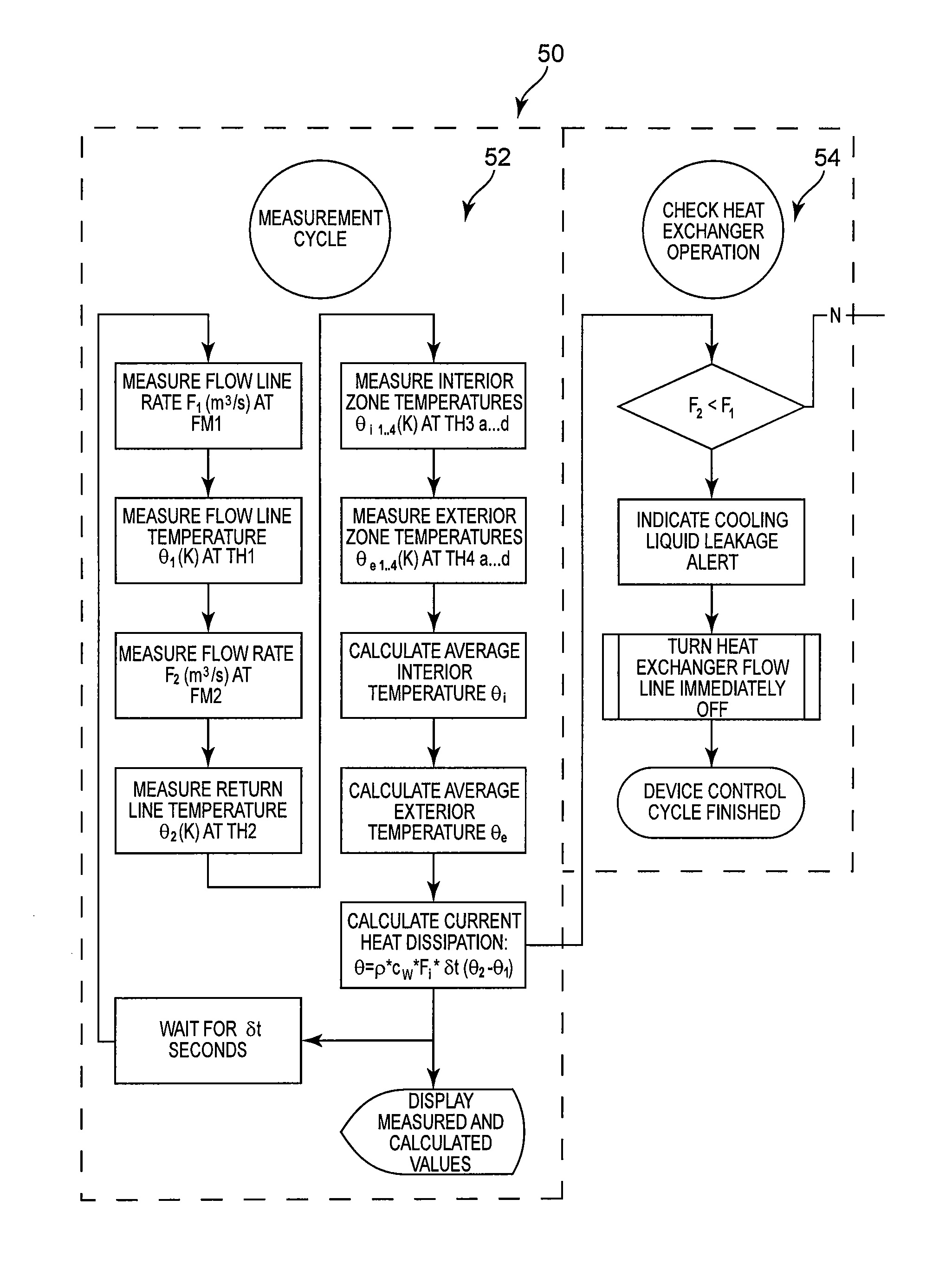
[0005]The present invention solves the foregoing problems by providing a method for controlling operation of a heat exchanger system comprising providing a heat exchanger system mountable to a rear door of a rack mounted computer system, circulating a heat transport medium through the heat exchanger system, detecting leaks in the heat exchanger system by comparing a first flow rate in an inflow line to a second flow rate in a return flow line, emitting a leakage alert and ceasing further circulation of the heat transport medium through the heat exchanger system when the first flow rate exceeds the second flow rate by a predetermined flow amount, optimizing operation of the rack mounted computer system by monitoring an interior temperature of the rack mounted computer system in a plurality of vertical zones, and optimizing operation of the heat exchanger system by comparing a second temperature measured by a second temperature sensor in the return flow line with a predetermined maximum return flow temperature value. Optimizing operation of the rack mounted computer system includes emitting a rack overheat alert and automatically increasing air flow through the heat exchanger system when the interior temperature in at least one of the vertical zones exceeds a maximum desirable interior temperature value, and automatically increasing a load level of the rack mounted computer system when the interior temperature in at least one of the vertical zones is less than a minimum desirable interior temperature value. Optimizing operation of the heat exchanger system includes automatically reducing flow of the heat transport medium through the heat exchanger and decreasing air flow from through the heat exchanger system when the second temperature is less than the predetermined maximum return flow temperature value, and automatically increasing flow of the heat transport medium through the heat exchanger and increasing air flow through the heat exchanger system when the second temperature is greater than or equal to the predetermined maximum return flow temperature value.

Problems solved by technology

The increased power requirements of today's computer systems leads to a proportionately increased heat load.
Generally speaking, the historically installed heating, ventilating, and air conditioning (HVAC) systems are not capable of keeping up with this growth.
One drawback of existing rear door heat exchangers is the need for an external monitoring system to detect failures.
These failures may include, for example, leakages and overheating of the equipment in the rack.
Both events can cause serious damage to the equipment and environment, and therefore, must be detected as soon as possible.
Because no human operator is present to guard against device failures in typical operating environments, these failures often go undetected for extended periods of time.
Thus, although there is a need for remote “alerts” in case of failures, existing rear door heat exchanger systems do not provide such a feature.

Method used


Image

  • Rear door heat exchanger instrumentation for heat quantity measurement
  • Rear door heat exchanger instrumentation for heat quantity measurement
  • Rear door heat exchanger instrumentation for heat quantity measurement

Examples


Embodiment Construction

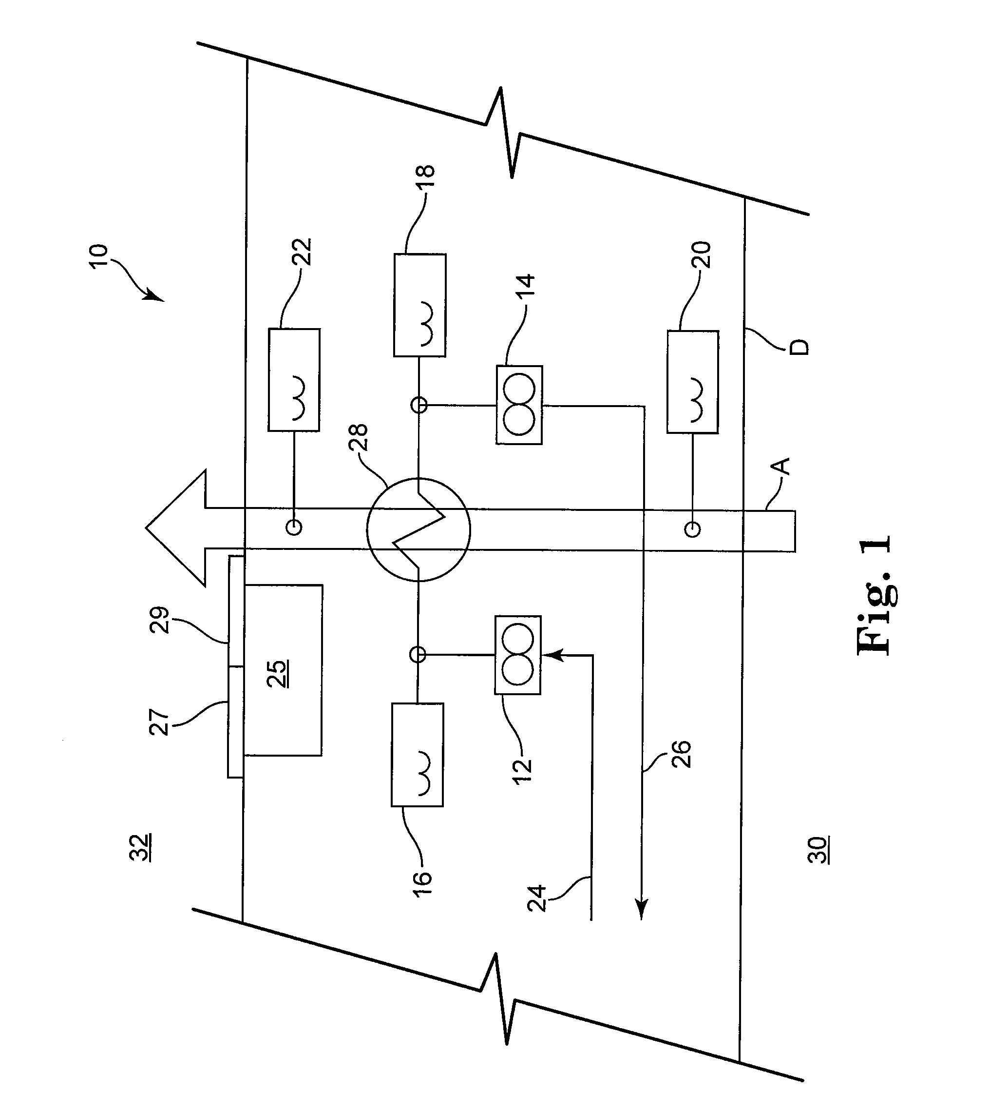
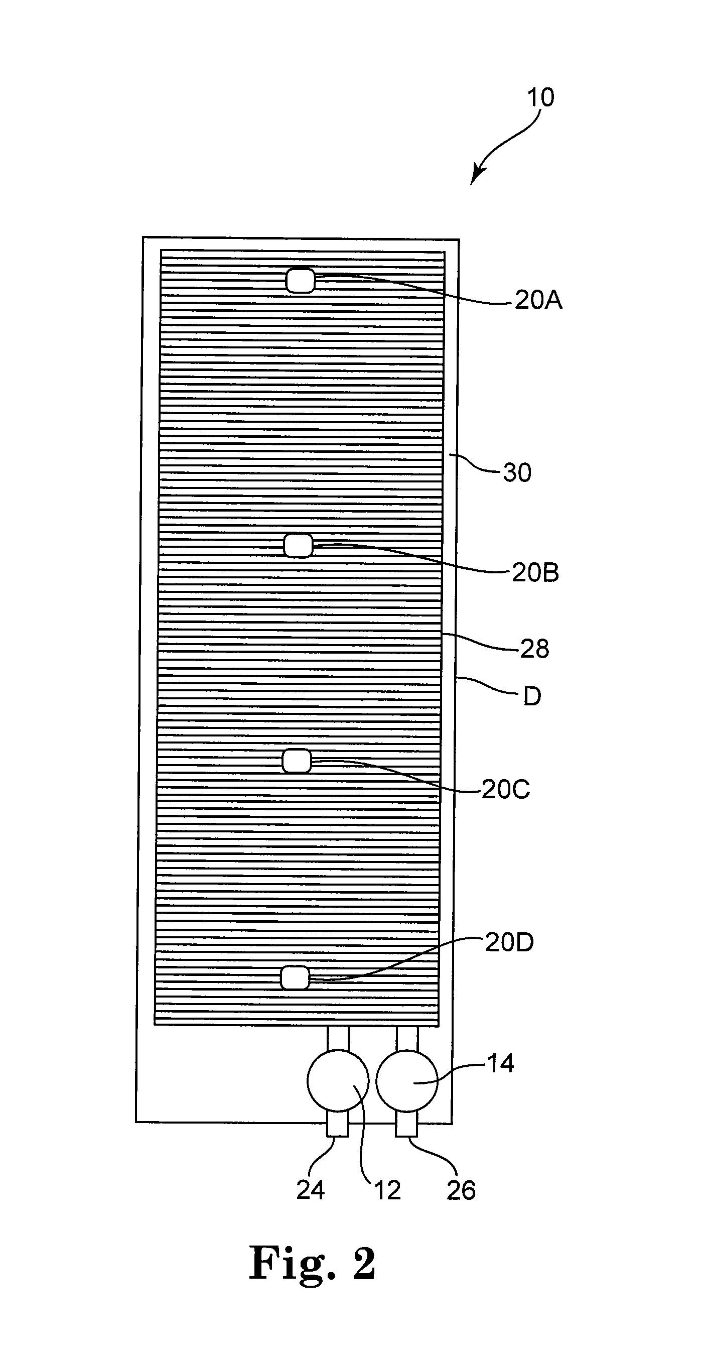
[0009]The present invention will be described in detail with reference to the figures below. However, generally speaking, the present invention is a rear door heat exchanger system having built-in sensors and a microcontroller with a central operator panel and display configured to measure temperature differences between the inside and the outside of the rear door, heat transport medium temperature, and flow rate. The microcontroller may be designed to consolidate and archive the measured data. By mounting the operator panel and display to the outside of the door, the working state may be monitored easily and at one location. Benefits provided by the integration of such a control system include, but are not limited to: measuring, archiving, and displaying the heat capacity dissipation of the heat exchanger; measuring, archiving, and displaying the proper operation of the heat exchanger; alerting operating personnel of failures in the system, such as by using blinking lights, sound a...


PUM


Abstract

A method for controlling operation of a heat exchanger system comprises providing a heat exchanger system mountable to a rear door of a rack mounted computer system, circulating a heat transport medium through the heat exchanger system, detecting leaks in the heat exchanger system by comparing a first flow rate in an inflow line to a second flow rate in a return flow line, emitting a leakage alert and ceasing further circulation of the heat transport medium through the heat exchanger system when the first flow rate exceeds the second flow rate by a predetermined flow amount, optimizing operation of the rack mounted computer system by monitoring an interior temperature of the rack mounted computer system in a plurality of vertical zones, and optimizing operation of the heat exchanger system by comparing a second temperature measured by a second temperature sensor in the return flow line with a predetermined maximum return flow temperature value.

Description

FIELD OF THE INVENTION[0001]The present invention relates in general to heat management, and more particularly, to a heat exchanger system and method for measuring and monitoring heat quantity in rack mounted computer systems.BACKGROUND OF THE INVENTION[0002]The increased power requirements of today's computer systems leads to a proportionately increased heat load. Generally speaking, the historically installed heating, ventilating, and air conditioning (HVAC) systems are not capable of keeping up with this growth. Rear door heat exchangers address this problem by cooling the air exhausted from rack mounted systems. These heat exchangers are primarily viewed as local cooling devices designed to treat particular hot spots. In particular, the heat exchangers absorb energy from the hot air flow from the computer system and transfer it into water. However, cooling of the air around the rack mounted system can also be viewed as a heating process from the point of view of the cooling cycl...

Claims


Application Information

Patent Timeline
Patent Type & Authority Patents(United States)
IPC IPC(8): G08B21/00
CPCF28F27/00H05K7/20836
Inventor GRIFFEL, MARCLEHMANN, MARK D.SCHAEFER, MICHAELUHL, KARL H.
Owner IBM CORP
Learn More