LED lamp cooling apparatus with pulsating heat pipe
a technology of led lamps and heat pipes, which is applied in the direction of lighting and heating apparatus, indirect heat exchangers, semiconductor devices of light sources, etc., can solve the problems of limited heat dissipation efficiency of led lamps, inconvenient for high-power consumption led lamps, and reduced work efficiency and service li
- Summary
- Abstract
- Description
- Claims
- Application Information
AI Technical Summary
Benefits of technology
Problems solved by technology
Method used
Image
Examples
first embodiment
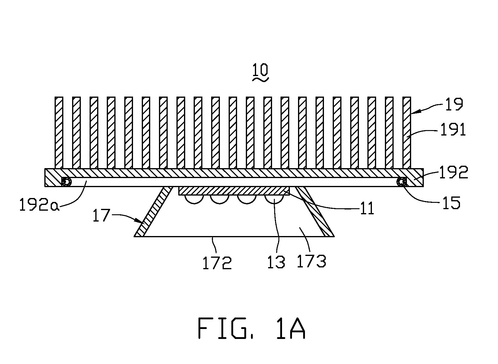
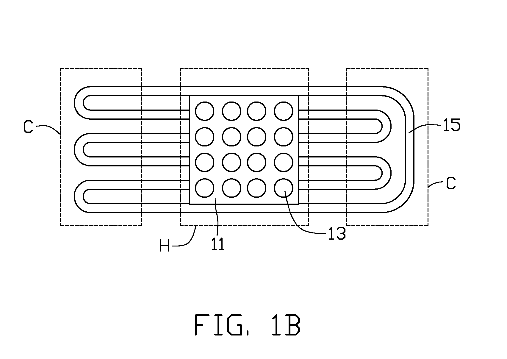
[0028]FIGS. 1A-1B illustrate an LED lamp cooling apparatus 10 in accordance with the present invention. The cooling apparatus 10 includes a substrate 11, a plurality of LEDs 13 electrically connected with the substrate 11, a pulsating heat pipe 15 thermally connected with the substrate 11, a reflector 17 enclosing the LEDs 13 and the substrate 11, and a heat sink 19 attached to the pulsating heat pipe 15 for dissipating heat generated by the LEDs 13 to ambient atmosphere. Shape and structure of the heat sink 19 can be diverse. In this embodiment, the heat sink 19 includes a planar base 192 and a plurality of cooling fins 191 extending upwardly from the base 192.
[0029]The substrate 11 of the cooling apparatus 10 is a circuit board preferably made of a highly thermally conductive material. The substrate 11 may be a metal-based circuit board, such as a metal core printed circuit board (MCPCB), to improve thermal conductivity. Alternatively, the substrate may be a ceramic circuit board....
fifth embodiment
[0040]FIGS. 7A-7B illustrate an LED cooling apparatus 70 in accordance with the present invention. The cooling apparatus 70 includes a substrate 71, a plurality of LEDs 73 electrically connected with the substrate 71, a reflector 77 enclosing the substrate 71 and the LEDs 73, a heat sink 79 and a pulsating heat pipe 75 thermally connected with both the substrate 71 and the heat sink 79.
[0041]The reflector 77 has a cup-like shape and is made of a material of high thermal conductivity such as copper or aluminum. The reflector 77 has a bottom chassis 772 on which the substrate 71 and the LEDs 73 are disposed, and defines an opening 771 at a top end thereof acting as a light exit. An inner surface of the reflector 77 has a light-reflecting material applied thereon, so that light emitted from the LEDs 73 can be reflected and guided towards the opening 771. The heat sink 79 has a U-shaped base 792 defining a recess 793 for the reflector 77 to be accommodated therein, and a plurality of co...
seventh embodiment
[0044]FIGS. 9A-9B illustrate an LED lamp cooling apparatus 90 in accordance with the present invention. In this embodiment, the pulsating heat pipe 95 is formed as a closed loop and is configured to have a shape conforming to the U-shaped profile of the reflector 97. Alternatively, the pulsating heat pipe 95 can also be an open loop as shown in FIG. 9C. The pulsating heat pipe 95 has a plurality of U-shaped heat receiving portions 954 in a central area thereof and a plurality of U-shaped heat radiating portions 955 at a circumference thereof. The reflector 97 is made of a highly thermally conductive material such as copper, aluminum or alloys thereof, and the pulsating heat pipe 95 is tightly and thermally attached to or embedded in an inner surface of the reflector 97. The heat receiving portions 954 and heat radiating portions 955 are evenly distributed across the inner surface of the reflector 97. The LEDs 93 are disposed on and electrically connects with the substrate 91. The su...
PUM
 Abstract
Description
Claims
Application Information
 - R&D
- Intellectual Property
- Life Sciences
- Materials
- Tech Scout
- Unparalleled Data Quality
- Higher Quality Content
- 60% Fewer Hallucinations
Browse by: Latest US Patents, China's latest patents, Technical Efficacy Thesaurus, Application Domain, Technology Topic, Popular Technical Reports.
© 2025 PatSnap. All rights reserved.Legal|Privacy policy|Modern Slavery Act Transparency Statement|Sitemap|About US| Contact US: help@patsnap.com


