
X-ray CT examination installation and CT method of examining objects

a technology of x-ray ct and installation, which is applied in the field can solve the problems of cost saving of x-ray ct examination installations, and achieve the effect of simplifying the installation of x-ray ct examination and facilitating the examination

Inactive Publication Date: 2009-06-09
YXLON INT X RAY
View PDF8 Cites 7 Cited by
  • Summary
  • Abstract
  • Description
  • Claims
  • Application Information

AI Technical Summary

Benefits of technology

This approach reduces the size and cost of X-ray CT installations, enables quicker examination of objects, and simplifies the examination process by allowing for the use of smaller detectors and more compact designs, while maintaining efficient data capture for objects of different sizes.

Problems solved by technology

This leads to a cost saving vis-à-vis the X-ray CT examination installations.

Method used


Image

  • X-ray CT examination installation and CT method of examining objects
  • X-ray CT examination installation and CT method of examining objects
  • X-ray CT examination installation and CT method of examining objects

Examples


Embodiment Construction

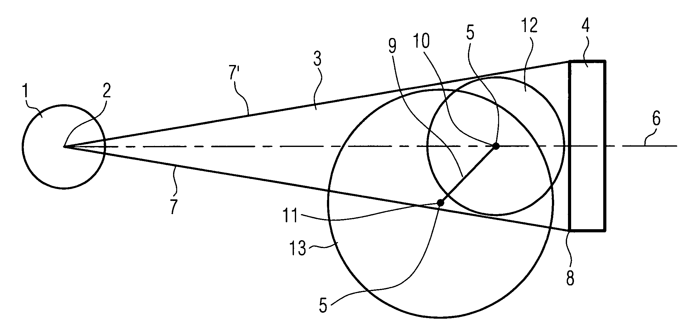
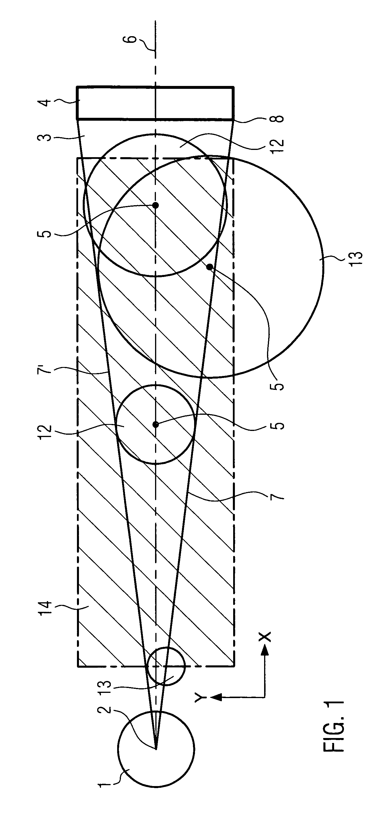
[0024]A top view of an X-ray CT examination installation is schematically represented in FIG. 1. An X-ray tube 1 has a focus 2 from which an X-ray beam in the form of a fan beam 3 emanates. This fan beam 3 meets a detector 4 the whole of which is X-rayed by the fan beam 3. Such an arrangement is well known from industrial CT. The distance between detector 4 and focus 2 can be varied in order to achieve as good as possible an image geometry for an object to be examined. As only a thin slice in the plane of the fan beam 3 of the object to be examined can be tomographed by the fan beam 3 both the X-ray tube 1 and also the detector 4 can be moved vertically. The object to be examined is X-rayed layer-by-layer. Alternatively it is also possible to vary the height of the object or to combine both methods.

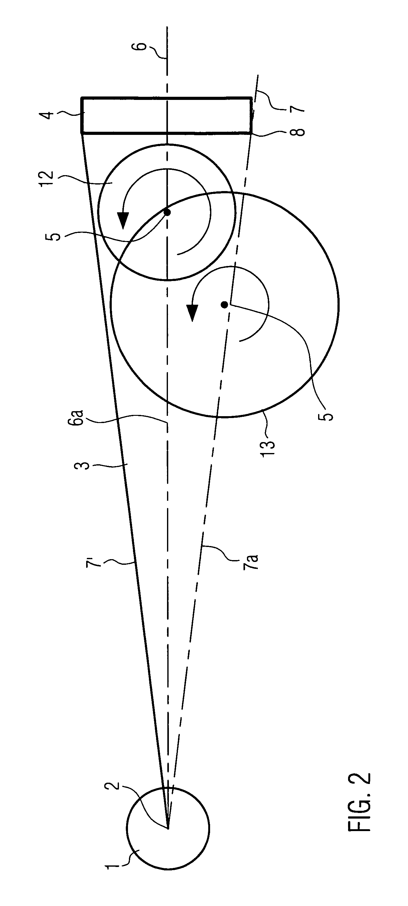
[0025]A carriage on which an object to be examined can be fixed is arranged between the focus 2 and the detector 4. The examination carriage rotates about an axis of rotation 5 which stan...


PUM

PropertyMeasurementUnit
aperture angleaaaaaaaaaa
rotation tomographyaaaaaaaaaa
distanceaaaaaaaaaa

Abstract

An X-ray CT examination installation, having an X-ray tube including a focus, that creates a fan beam or a conical beam which X-rays the whole of a detector at a fixed distance from the focus, and an examination carriage, for supporting an object to be examined, the carriage having an axis of rotation perpendicular to the fan beam, wherein the examination carriage can be fixed inside the fan beam close to an edge axis which meets the detector at the edge, and can be moved on a measuring line that centrally runs at an angle to a central axis which meets the detector.The invention also relates to a CT method of examining objects, in particular of various sizes, by means of an X-ray CT examination installation generally identified above.

Description

CROSS-REFERENCE TO RELATED APPLICATION[0001]This is a utility application that claims foreign priority benefits under 35 USC §119 (a) to German Patent Application No. DE 10 2005 036 527.2, filed 3 Aug. 2005, which application is incorporated herein by reference.BACKGROUND OF THE INVENTION[0002]The invention relates to an X-ray CT examination installation, with an X-ray tube with a focus, which creates a fan beam or a conical beam which X-rays the whole of a detector at a fixed distance from the focus, and with an examination carriage, for recording an object to be examined, which has an axis of rotation rotatable perpendicular to the fan beam. The invention also relates to a CT method of examining objects, in particular of various size, by means of an above-named X-ray CT examination installation.[0003]There are currently two examination methods in industrial computed tomography (CT). One is a translation / rotation tomography and the other a rotation tomography. In both cases a fan b...

Claims


Application Information

Patent Timeline
Patent Type & Authority Patents(United States)
IPC IPC(8): G01N23/00
CPCG01N23/046G01N2223/419
Inventor MUNKER, MARTINROKITTA, OLIVERLAAKEL, FAISSAL
Owner YXLON INT X RAY
Learn More