Spot drilling insert

a drilling insert and insert technology, applied in the field of cutting tools, can solve the problems of cutting edges that are not sufficiently centering and guiding for drills with very small diameters, and the pilots formed by drills with points in excess of 100° may not have enough centering and guidance for very small drills

Active Publication Date: 2009-06-02
CENTURY TOOL & DESIGN
View PDF32 Cites 17 Cited by
  • Summary
  • Abstract
  • Description
  • Claims
  • Application Information

AI Technical Summary

Benefits of technology

[0013]A still further object of the present invention is to provide a new and improved drill poin

Problems solved by technology

Removing the twist drill often requires a time consuming re-calibration of the machine tool.
Pilots formed by drills having point angles in excess of 100° may not have sufficient centering and guidance for very small diame

Method used


Image

  • Spot drilling insert
  • Spot drilling insert
  • Spot drilling insert

Examples


Embodiment Construction

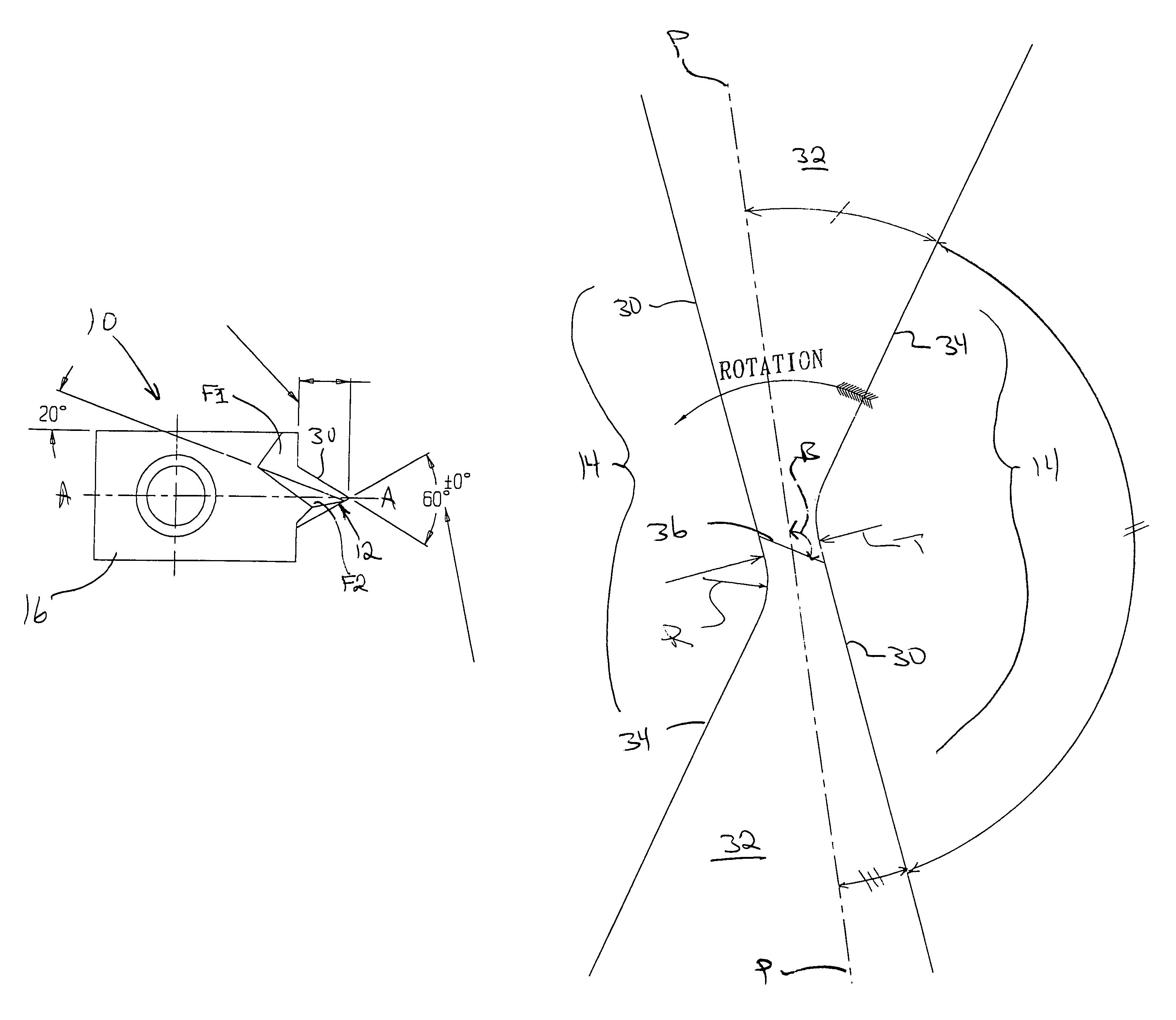
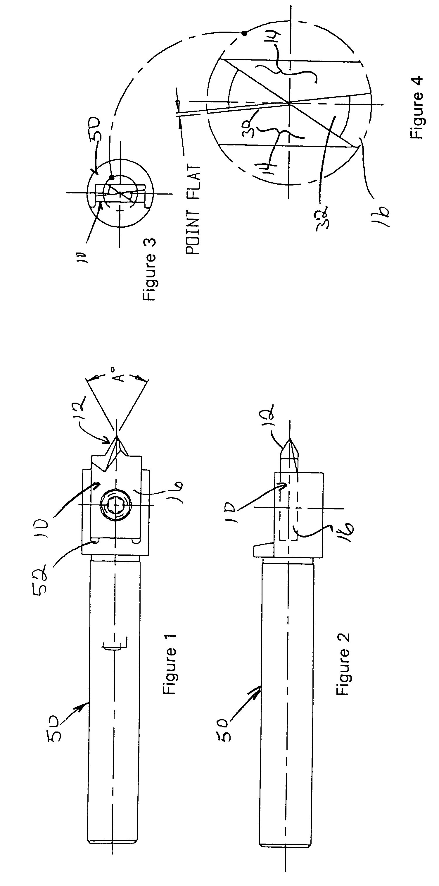
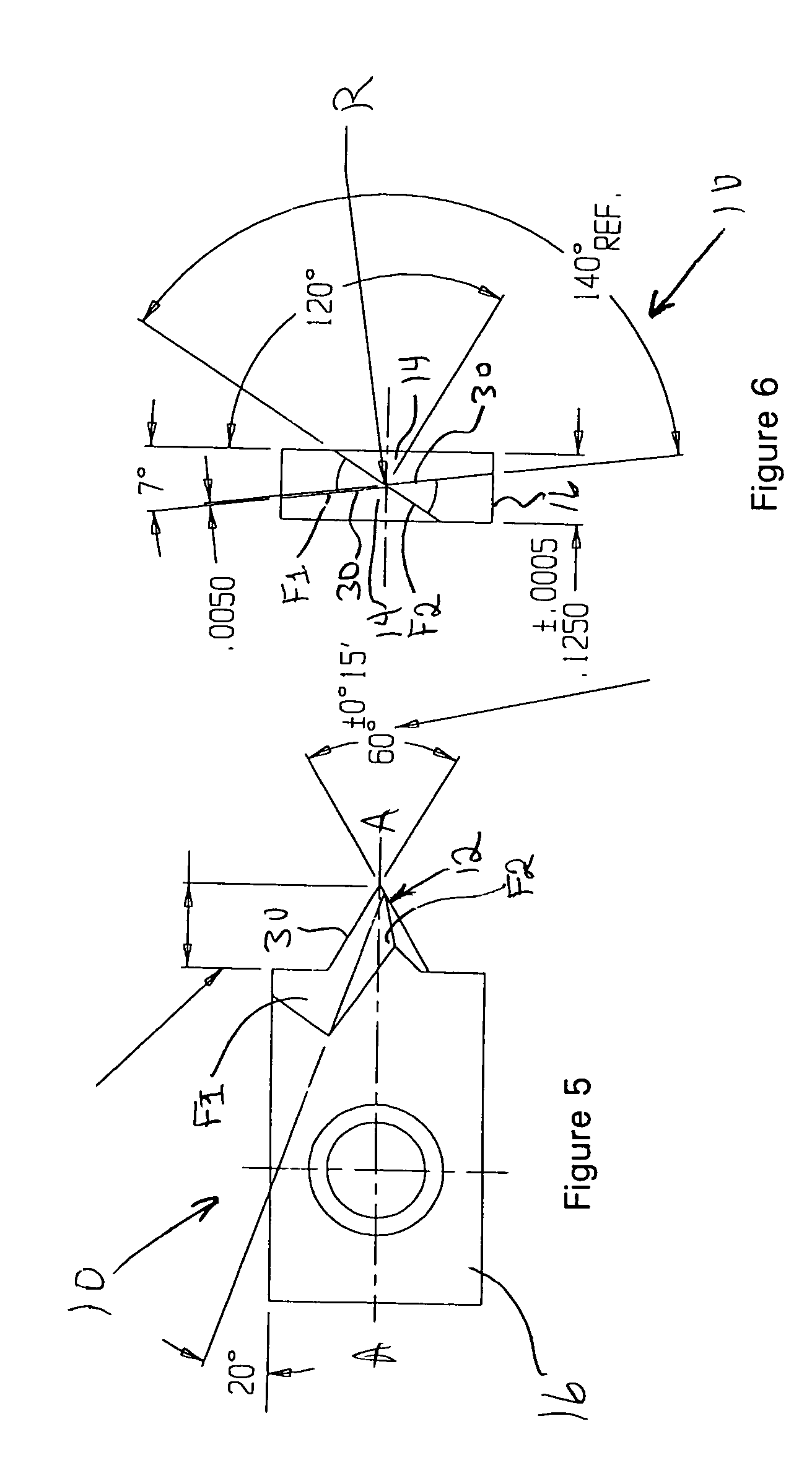
[0023]With reference to the drawings, wherein like numerals indicate like parts throughout the several figures, a spot drilling insert exemplary of aspects of the present invention is generally designated by the numeral 10. FIGS. 1-3 illustrate a drill holder 50 in conjunction with a spot drilling insert 10 according to aspects of the present invention. The drill holder 50 defines a socket that is configured to receive and secure the spot drilling insert. The insert 10 includes a tapered mounting hole that receives a mounting screw having a complementary taper. The tapered hole and screw ensure contact between mounting surfaces of the insert and the bottom and rear surfaces of the socket to consistently position the insert 10 relative to the holder 50. The rear, side and bottom mounting faces of the insert 10 are ground to very close tolerances so that exchanging one spot drilling insert for another positions the drill point of the new insert substantially in the same location as th...


PUM

PropertyMeasurementUnit
Angleaaaaaaaaaa
Angleaaaaaaaaaa
Angleaaaaaaaaaa

Abstract

A spot drilling tool includes a drill holder and an insert removably mounted to the holder. The insert is a standardized part configured to support a drill point in a predetermined position forward of the drill holder and centered on the rotational axis of the drill holder. The drill point has two flutes and two substantially conical land surfaces extending between the flutes. The land surfaces have centers of curvature offset from the rotational axis of the insert to provide radial clearance for the trailing portion of the land. A chisel edge at the tip of the drill point is supported by a tapered web defined between the diagonally opposed and offset flutes. Linear cutting edges are formed at the junction of a planar flute surface and the conical land surface. The cutting edges define a narrow included point angle of between 50° and 80°.

Description

FIELD OF THE INVENTION[0001]The present invention generally relates to the field of cutting tools and more particularly to a spotting drill insert with improved point geometry.DESCRIPTION OF THE RELATED ART[0002]Hole making is the most common machining process, consuming 50 to 70 percent of all production time. Differences in material, hole diameter, depth, location and surface finish make each hole making operation unique. The selection of the proper machine tool, cutting tool, point geometry, feed rate, cutting speed and feed force have a significant impact on the efficiency of the hole making operation and the quality of the resulting holes. Drilling holes with a diameter of less than 0.010 inches, sometimes called “micro drilling”, is a particularly demanding type of hole making. The tiny drills used to make these holes require an accurately placed and configured spot or pilot hole to position the drill point on the workpiece so it won't walk. The pilot hole also acts as a guide...

Claims


Application Information

Patent Timeline
IPC IPC(8): B23B13/00
CPCB23B51/0063B23P15/32B23B2224/24B23B2224/36B23B2228/10B23B2251/426Y10T408/901Y10S408/713Y10T408/899Y10T408/9065B23B2251/50B23B51/011
Inventor HOULE, JACQUES H.
Owner CENTURY TOOL & DESIGN
Why Eureka
Try Eureka