
Force and position control for active front steering

a technology of active front steering and position control, which is applied in the direction of fluid steering, electric steering, vehicle components, etc., can solve the problems of deteriorating the torque felt by the driver, less reaching capabilities, and other adverse effects

Inactive Publication Date: 2009-05-12
GM GLOBAL TECH OPERATIONS LLC +1
View PDF37 Cites 23 Cited by
  • Summary
  • Abstract
  • Description
  • Claims
  • Application Information

AI Technical Summary

Benefits of technology

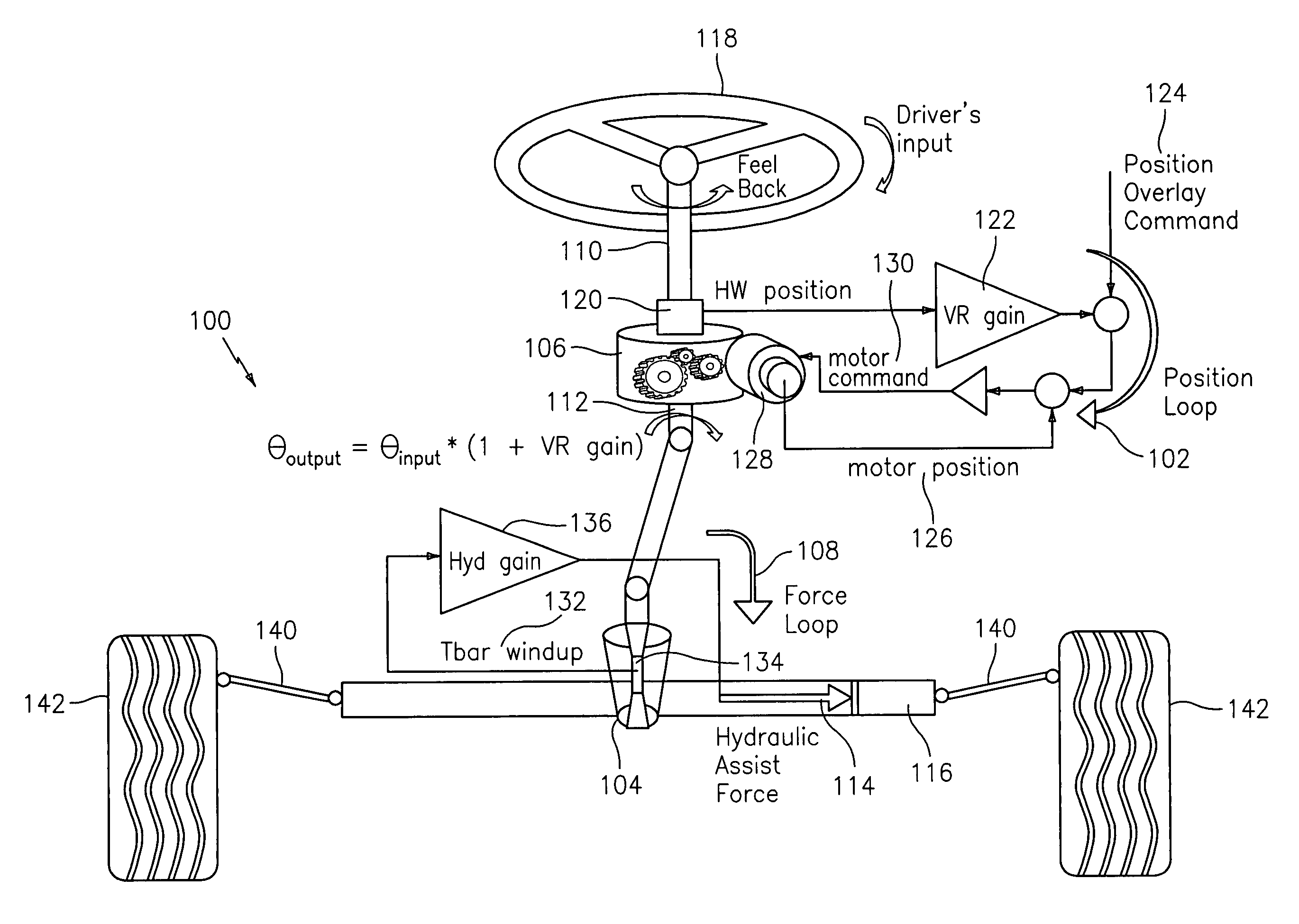
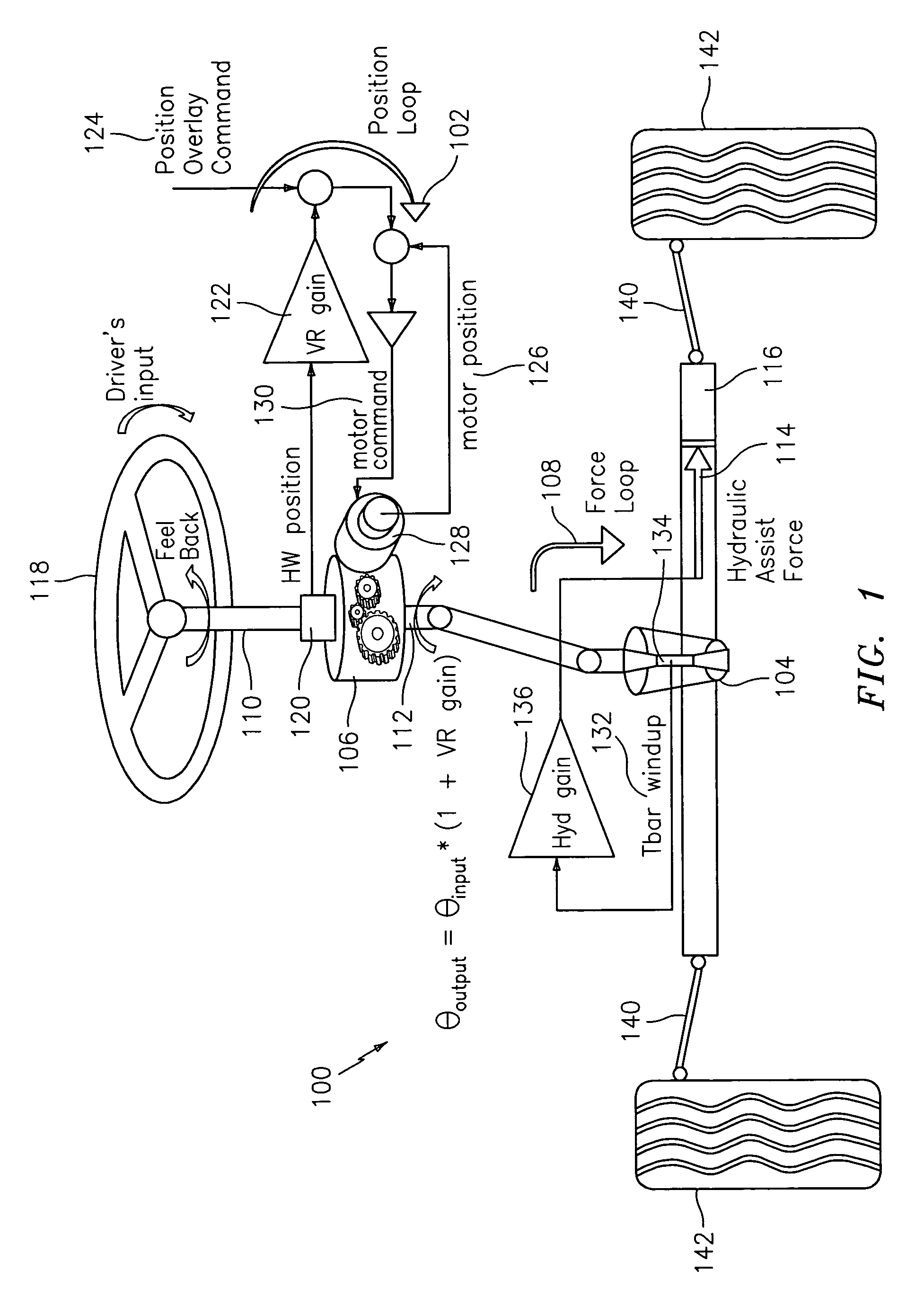
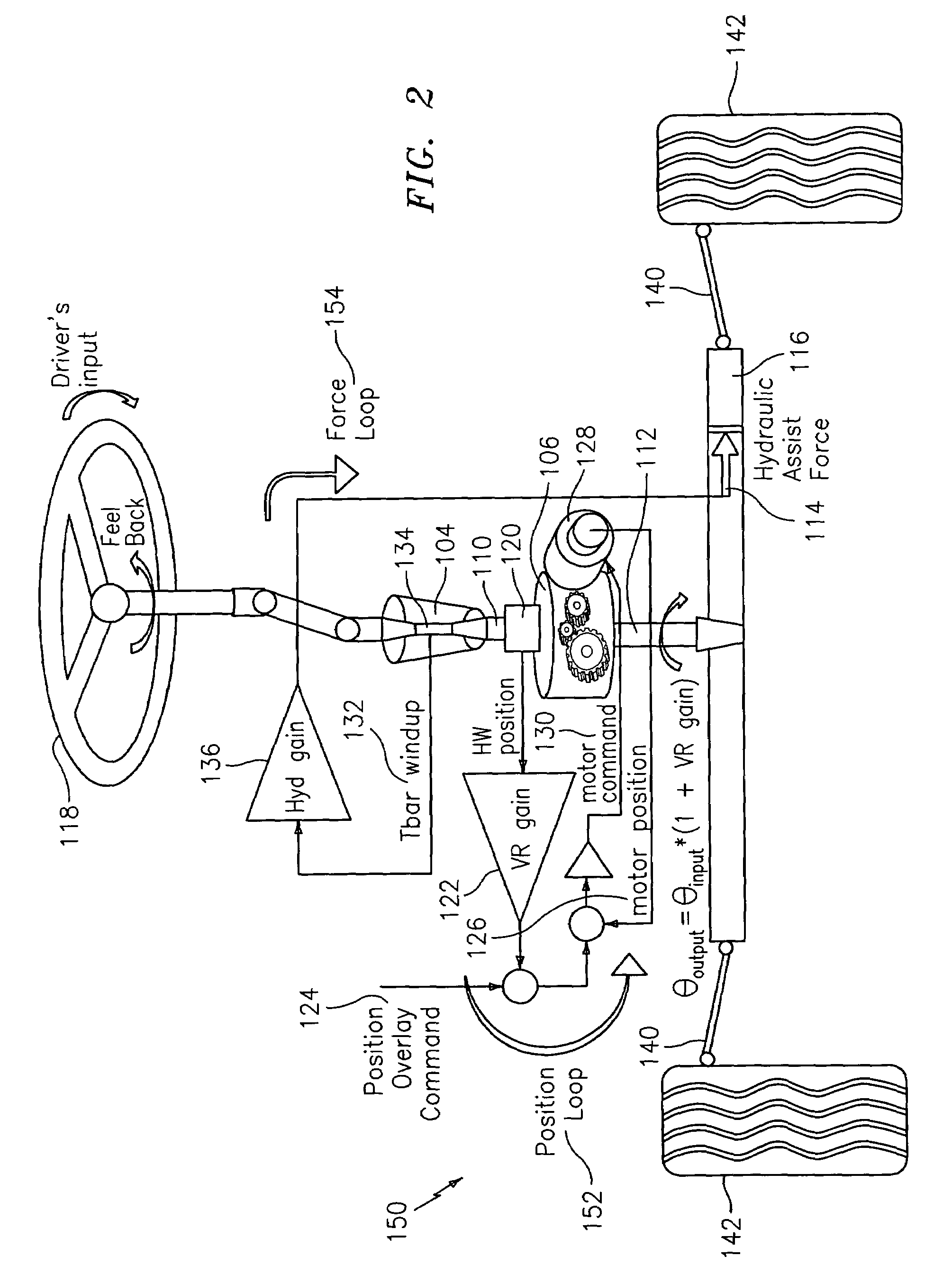
The patent describes a steering system that includes an input shaft, a torsion bar, a differential, a rack and pinion, a primary actuator, and a secondary actuator. The system also includes a position overlay unit for applying assist force to either the rack or the motor, and an electric power mechanism or hydraulic power mechanism for providing the assist force to the rack. The technical effect of this system is to provide better steering performance and control for vehicles.

Problems solved by technology

Tunable and customer selectable variable ratio steering and driver effort can be achieved with some existing steering systems, yet these functions are less reaching capabilities since outcomes (variable effort or variable ratio steering) are directly functions of driver input torque and position.
As one achieves torque or position overlay functionalities, one could find that the other be adversely affected.
For example, a position overlay system that helps with a vehicle's stability may subjectively deteriorate the torque felt by the driver and thus the torque overlay functionality.
For the time being, the mechanizations in a steer-by-wire system are very expensive due to backup sensors and / or backup actuation systems, and the stringent (in terms of friction, lash, accuracy, etc.) requirements for the sensors and actuator components.
Since there is a mechanical connection and it is in series with both the assist control mechanism and the driver input device, torque feedback to the driver during road wheel augmentation is a design challenge.
The consequence of these modifications, however, is a torque that's fed back to the driver (perhaps undesirable).
This torque (or force) feedback can be reduced as one increases the assistive power, however, an increase in assist may not be feasible or desirable.

Method used


Image

  • Force and position control for active front steering
  • Force and position control for active front steering
  • Force and position control for active front steering

Examples


Embodiment Construction

[0026]Embodiments of the steering systems described herein support advantages of autonomous control of the front wheels and achieve acceptable torque feedback with feasible and less expensive components than current applications. The steering systems described herein can therefore be used for future applications. The mechanizations described within at least some of the steering systems described herein can operate under different modes such as steer-by-wire, active front steering, and electric power steering.

[0027]In a mechanically linked steering system, one cannot simultaneously control the position (or force) at both the road wheels and hand wheel. If one chooses to control the force at one end, one will need to control the position at the other end, and visa versa. These control loops, unfortunately, are not independent. The more precise the control on one end has the consequence of a less precise (or desirable) control on the other end. Steering systems are traditionally design...


PUM


Abstract

A steering system with reduced coupling between a position overlay unit and a torque overlay unit may include a remote valve assembly for controlling a hydraulic assist force or an electric motor for providing torque overlay and electric assist to a rack of a rack and pinion steering system. In one embodiment, the position overlay unit may provide the assist force and the torque overlay unit may provide a motor command signal to the motor of a differential positioned on a steering shaft. In another embodiment, the position overlay unit may provide the motor command signal and the torque overlay unit may provide the assist force. In either embodiment, the position overlay unit may include variable ratio gain that uses a position signal to output a variable ratio command.

Description

CROSS REFERENCE TO RELATED APPLICATIONS[0001]This application claims priority to U.S. Provisional Application No. 60 / 611,225, filed Sep. 17, 2004, and U.S. Provisional Application No. 60 / 630,514, filed Nov. 23, 2004, both incorporated by reference in their entirety.FIELD OF THE INVENTION[0002]This invention relates to a steering system, and more particularly, this invention relates to an active front steering system with a capability to independently control driver's effort and positioning of the steerable device.BACKGROUND[0003]Vehicles require a steering system to control the direction of travel. Steering systems typically include a mechanical linkage or a mechanical connection between a steering input device (e.g. a hand wheel) and the vehicle's steerable device (e.g. road wheels). Thus, mechanical movement of the steering input device causes a corresponding mechanical movement of the steerable device. Movement of such mechanical systems is often power-assisted through the use of...

Claims


Application Information

Patent Timeline
Patent Type & Authority Patents(United States)
IPC IPC(8): B62D5/04
CPCB62D5/008B62D5/0463B62D5/0472B62D5/06B62D5/09
Inventor BOLOURCHI, FARHADAUGUSTINE, MICHAEL J.MAGNUS, BRIAN J.DEMERLY, JON D.AMBERKAR, SANKET S.OZSOYLU, SUAT A.CARD, JAMESBOSWELL, KAREN
Owner GM GLOBAL TECH OPERATIONS LLC
Learn More