Magnetoresistance effect element having a lower magnetic layer formed over a base substrate through a transition metal oxide layer having a predetermined orientation plane

a transition metal oxide and element technology, applied in the field of magnetoresistance effect elements, can solve the problems of difficult to obtain a good crystallinity ferromagnetic layer, difficult to form an epitaxial film on such an insulating layer, etc., and achieve excellent crystallinity, convenient epitaxial growth, and high mr ratio

Inactive Publication Date: 2009-04-21
SEIKO EPSON CORP
View PDF18 Cites 7 Cited by
  • Summary
  • Abstract
  • Description
  • Claims
  • Application Information

AI Technical Summary

Benefits of technology

[0011]With the structure described above, because the lower magnetic layer is formed on the transition metal oxide layer formed with a predetermined orientation plane, the lower magnetic layer can be crystal-grown excellently on the transition metal oxide layer, such that the magnetoresistance effect element can be provided with an excellent magnetic characteristic. Accordingly, the MR ratio of the element can be improved, and the magnetoresistance effect element can be provided with excellent noise characteristic and operation stability.
[0035]In the magnetic memory device in accordance with the present invention, the magnetoresistance effect element may preferably be formed through a buffer layer over the base substrate, and the plurality of the memory cells may preferably commonly share the buffer layer. With this structure, because each of the memory cells shares the buffer layer, the magnetoresistance effect elements of the respective memory cells have few variations in their characteristic, and have a large operation margin. By this, a magnetic memory device that is capable of stable operation can be provided.

Problems solved by technology

However, the ferromagnetic layer is generally formed on an insulating film that is composed of an oxide having an amorphous structure such as silicon oxide, and it is difficult to form an epitaxial film on such an insulating layer.
Accordingly, there is a problem in that it is difficult to obtain a ferromagnetic layer having a good crystallinity.

Method used


Image

  • Magnetoresistance effect element having a lower magnetic layer formed over a base substrate through a transition metal oxide layer having a predetermined orientation plane
  • Magnetoresistance effect element having a lower magnetic layer formed over a base substrate through a transition metal oxide layer having a predetermined orientation plane
  • Magnetoresistance effect element having a lower magnetic layer formed over a base substrate through a transition metal oxide layer having a predetermined orientation plane

Examples


Embodiment Construction

[0042]Magnetoresistance Effect Element

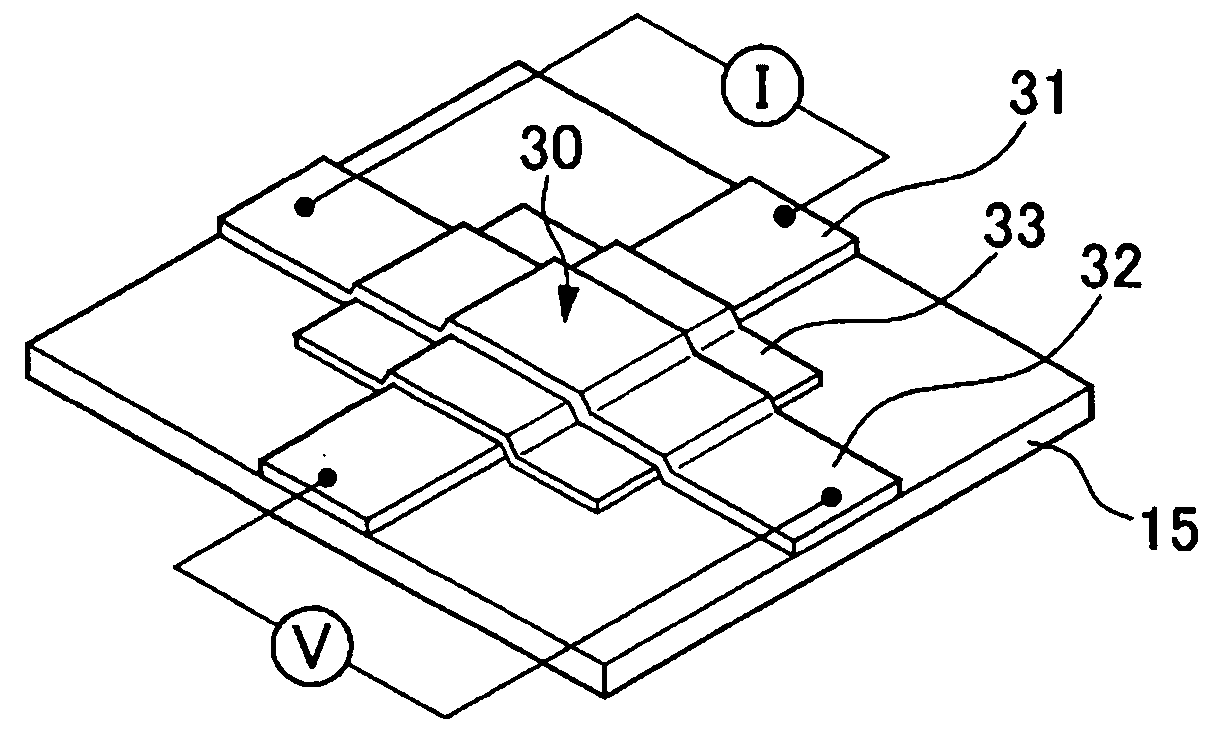
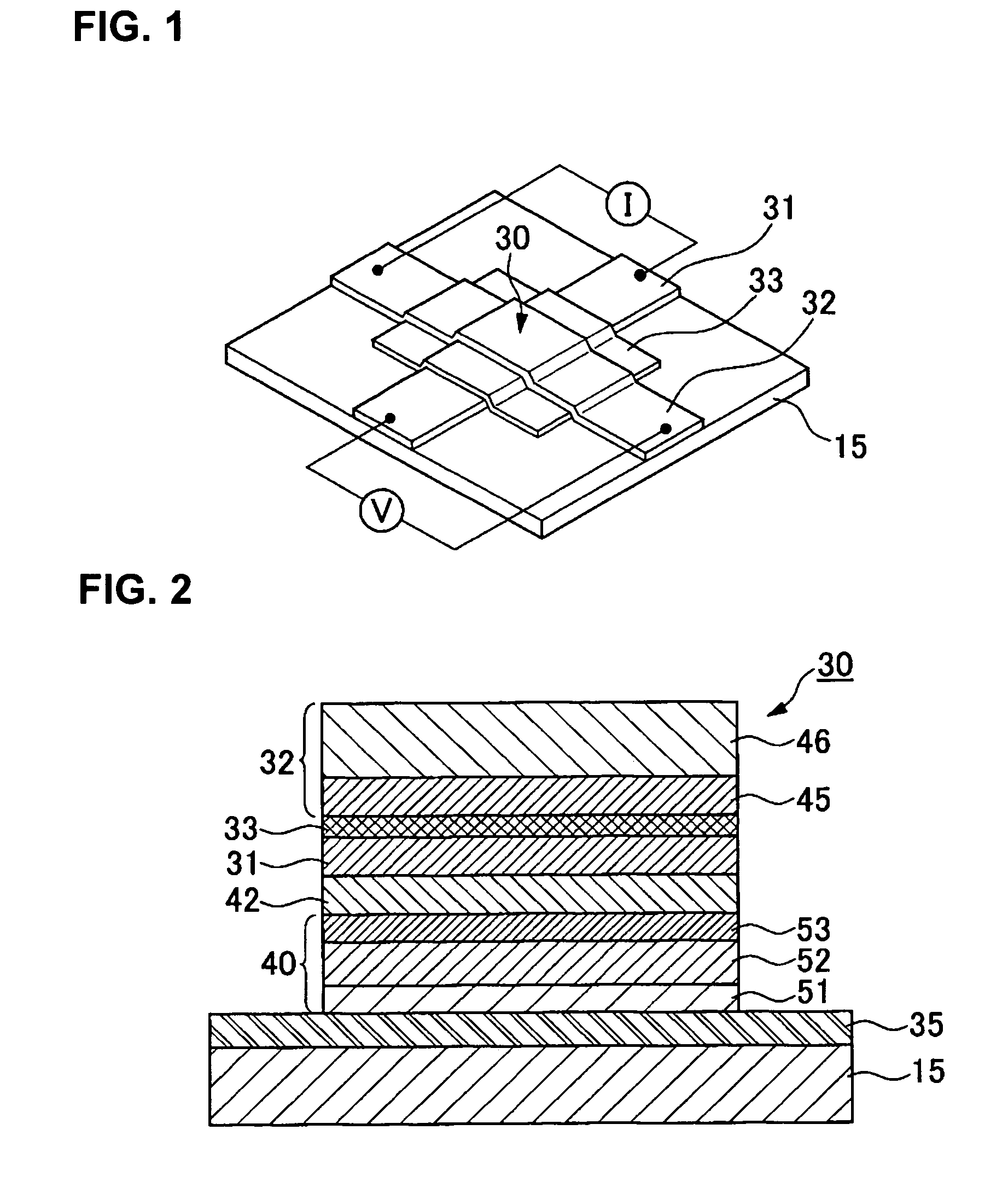
[0043]Embodiments of the present invention are described with reference to the accompanying drawings. FIG. 1 is a perspective structural view of a tunneling type magnetoresistance effect element (hereafter abbreviated as a TMR element) in accordance with an embodiment of the present invention, and FIG. 2 is a cross-sectional structural view of a TMR element 30 shown in FIG. 1.

[0044]As shown in FIG. 1, the TMR element 30 has a structure in which an insulating layer 33 is sandwiched between a memory layer (lower magnetic layer) 31 and a fixed magnetic layer (upper magnetic layer) 32 disposed mutually crossing one another over a substrate (base substrate) 15, and is formed at a position corresponding to an intersection between the memory layer and the fixed magnetic layer. In its cross-sectional structure, the TMR element 30 has a structure shown in FIG. 2 in which a buffer layer 40, a transition metal oxide layer 42, the memory layer 31, the insul...


PUM

PropertyMeasurementUnit
thicknessaaaaaaaaaa
thicknessaaaaaaaaaa
thicknessaaaaaaaaaa

Abstract

A magnetoresistance effect element is provided and includes a memory layer, an insulating layer and a fixed magnetic layer successively stacked on a substrate. The memory layer is formed on the substrate through a transition metal oxide layer having a predetermined orientation plane. A buffer layer is preferably provided on a lower layer side of the transition metal oxide layer.

Description

RELATED APPLICATIONS[0001]This application claims priority to Japanese Patent Application No. 2004-005412 filed Jan. 13, 2004 which is hereby expressly incorporated by reference herein in its entirety.BACKGROUND[0002]1. Technical Field[0003]The present invention relates to magnetoresistance effect elements and methods for manufacturing the same, and magnetic memory devices.[0004]2. Related Art[0005]In recent years, magnetic memory devices (MRAMs: Magnetic Random Access Memories) are attracting attention as memory devices that can be alternatives to DRAMs (Dynamic Random Access Memories) and SRAMs (Static Random Access Memories). MRAM are advantageous because they are nonvolatile, and capable of high-speed operations and higher recording density, and therefore are viewed as promising data storage memories and system memories for portable electronic equipment (see, for example, Wang et al., IEEE Trans Magn. 33 (1997), 4498).[0006]A MRAM is equipped with tunneling magnetoresistance ele...

Claims


Application Information

Patent Timeline
Patent Type & Authority Patents(United States)
IPC IPC(8): G11B5/127H01F10/20G11B5/33G11C11/14G11C11/15G11C11/16H01F10/193H01F10/32H01F41/30H01L21/8246H01L27/105H01L43/08H01L43/10H01L43/12
CPCB82Y25/00B82Y40/00G11C11/16H01F10/3254H01F41/302H01L27/228H01L43/08H01L43/12H01F10/1933H01F1/401H10B61/22H10N50/01H10N50/10
Inventor MIYAZAWA, HIROMUHIGUCHI, TAKAMITSUIWASHITA, SETSUYA
Owner SEIKO EPSON CORP
Why Eureka
Try Eureka