Transom drain light
a drain light and drain pipe technology, applied in the field of underwater lighting, can solve the problems of high cost, high cost, and require professional installation, and achieve the effect of low cost and easy removal from the vessel
- Summary
- Abstract
- Description
- Claims
- Application Information
AI Technical Summary
Benefits of technology
Problems solved by technology
Method used
Image
Examples
first embodiment
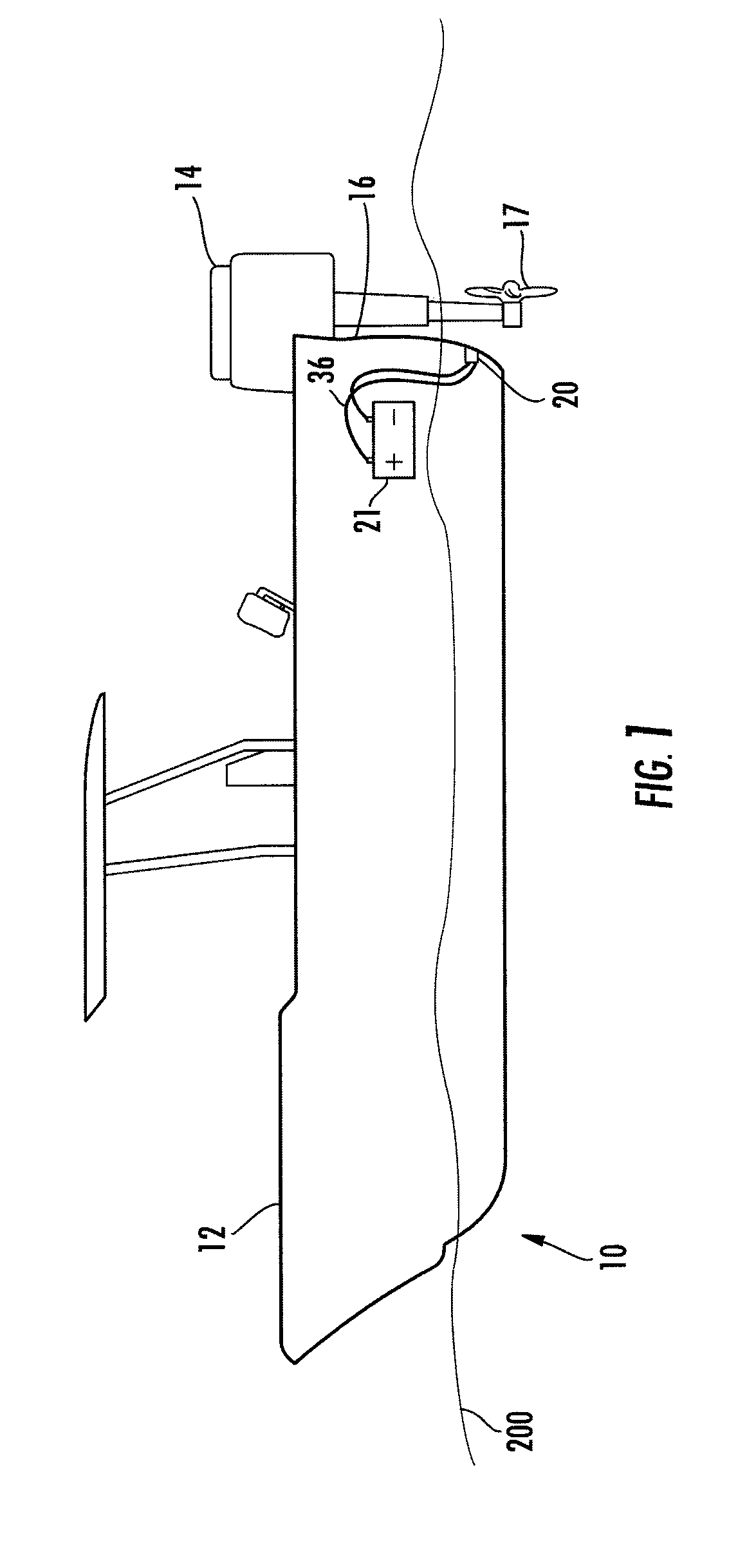
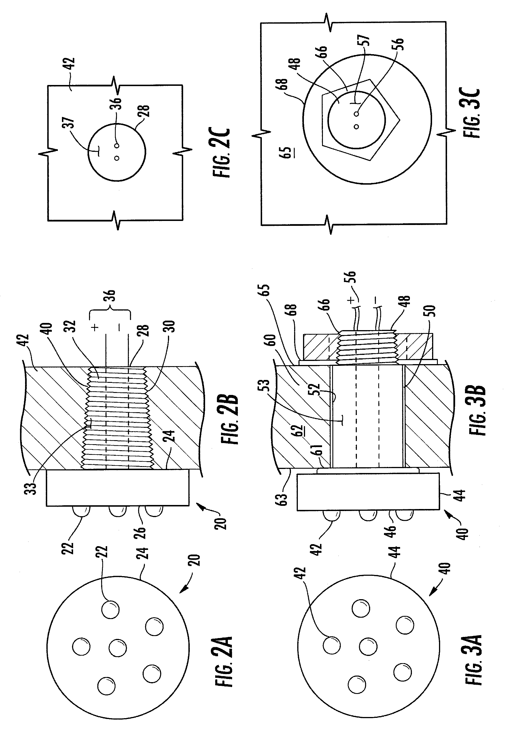
[0035]Now referring to FIG. 2a, 2b, and 2c shown is the instant invention wherein the transom drain light (20) includes at least one light-emitting diode (LED) (22) mounted in a support structure (24). The support structure has a first end (26) and a second end (28) with a continuous side wall (30) formed therebetween. The support structure may be sized to hold a single LED or a plurality of LED's. The support structure (24) may be square, round, semi-round shape, or have an ornamental shape such as a fish, boat, tree and so forth.
[0036]An inner surface (32) of the side wall (30) forms a chamber 33 that operates as a passageway for the electrical wires(36). The electrical wires are potted 37 within the chamber 33 to prevent chafing and water passage. The wires are preferably potted 37 with an isolating material such as natural or synthetic elastomers, nitro rubber, fluoroelastomers, silicone, or plastic. The outer surface (30) of the side wall is sized to sealingly secure to the tra...
second embodiment
[0037]Now referring to FIG. 3a, 3b, and 3c shown is the instant invention wherein the transom drain light (40) includes at least one light-emitting diode (LED) (42) mounted in a support structure (44). The support structure has a first end (46) and a second end (48) with a continuous side wall (50) formed therebetween. The support structure (44) may be square, round, semi-round shape, or have an ornamental shape.
[0038]An inner surface (52) of the side wall (50) forms a chamber 53 that operates as a passageway for the electrical wires(56). The electrical wires are potted (57) within the chamber (53) to prevent chafing and water passage. The wires are preferably potted (57) with an isolating material as mentioned above. The outer surface of the side wall (50) is sized to sealingly secure to the transom drain hole (60) of a marine vessel transom (62). In this embodiment the outer surface (50) is smooth thus requiring first seal (61) between the support (46) and outer transom wall (63);...
third embodiment
[0039]Now referring to FIG. 4a, 4b, and 4c shown is the instant invention wherein the transom drain light (80) includes at least one light-emitting diode (LED) (82) mounted in a support structure (84). The support structure has a first end (86) and a second end (88) with a flexible side wall (90) formed therebetween. The support structure (84) may be square, round, semi-round shape, or have an ornamental shape.
[0040]An inner surface (92) of the side wall (90) forms a chamber (93) that operates as a passageway for the electrical wires(96). The electrical wires are sealed (97)within the chamber (93) to prevent chafing and water passage. The outer surface of the side wall (90) is made of a flexible material, such as neoprene, that is sized to sealingly secure to the transom drain hole (100) of a marine vessel transom (62). In this embodiment the outer surface side wall (90) engages the drain hole by use of a means for expanding such as a conventional flip handle style tightening lever ...
PUM
 Abstract
Description
Claims
Application Information
 - R&D
- Intellectual Property
- Life Sciences
- Materials
- Tech Scout
- Unparalleled Data Quality
- Higher Quality Content
- 60% Fewer Hallucinations
Browse by: Latest US Patents, China's latest patents, Technical Efficacy Thesaurus, Application Domain, Technology Topic, Popular Technical Reports.
© 2025 PatSnap. All rights reserved.Legal|Privacy policy|Modern Slavery Act Transparency Statement|Sitemap|About US| Contact US: help@patsnap.com


