
Imaging systems and methods to improve backscattering imaging using circular polarization memory

a technology of backscattering imaging and imaging system, applied in angiography, optical radiation measurement, instruments, etc., can solve the problems of blurry image quality of artery surface and subsurface, laser surgery and laser cauterizing tissue normally is accompanied by the unwanted production of cloud of smoke and vaporized particles

Inactive Publication Date: 2009-04-07
RES FOUND THE CITY UNIV OF NEW YORK
View PDF11 Cites 20 Cited by
  • Summary
  • Abstract
  • Description
  • Claims
  • Application Information

AI Technical Summary

Benefits of technology

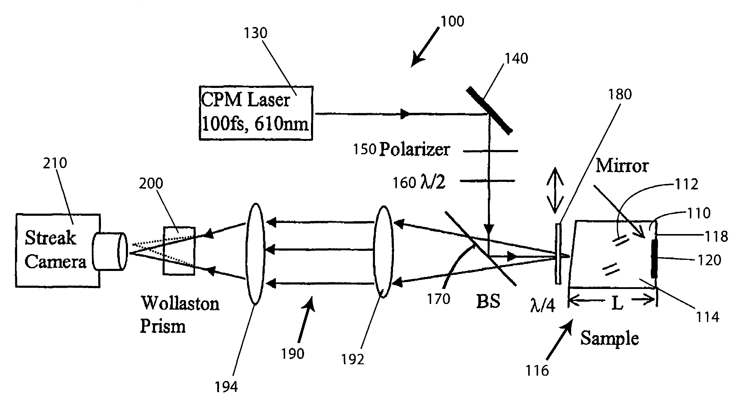
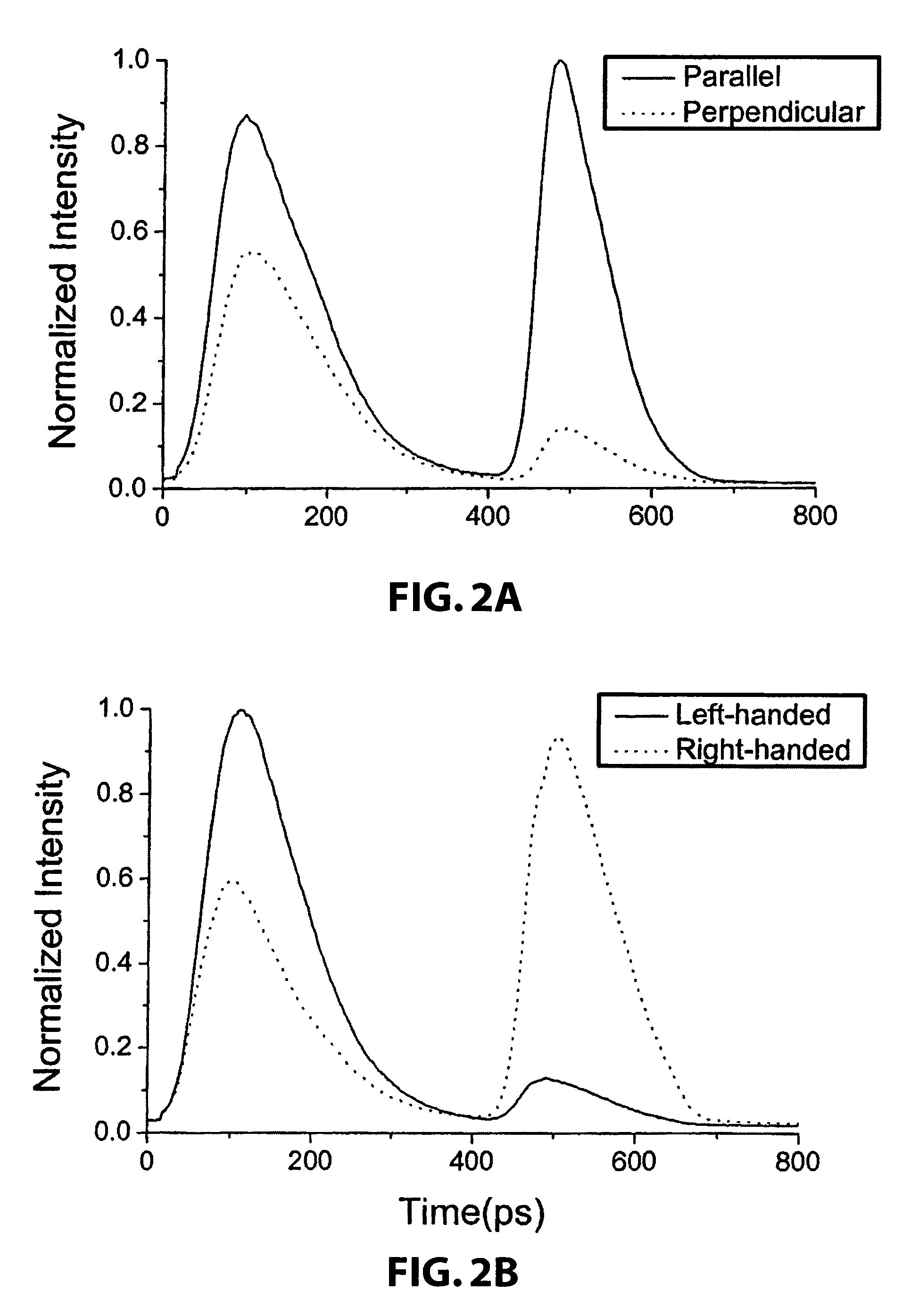
[0012]According to one embodiment of the present invention, a target inside a turbid medium formed with large particle suspensions is illuminated with circularly polarized light. By selecting out the backscattered light with opposite helicity (which represents main target information accompanied by low background light), the image contrast is significantly improved in comparison to imaging based on a linear polarization technique. This combination of circular polarization states permits an instrument of the system to be used for diverse applications, such as imaging through biological tissues and atmospheric environments in which the wavelength is less than the size of the scattering particles (λ<a).

Problems solved by technology

Each of these methods exhibits some relative strengths and limitations / deficiencies.
A major challenge of optical imaging is that the scattering effect from the blood, especially from the red blood cells with an average diameter of 7.65 μm, blurs the image quality of the artery surface and subsurface.
However, laser surgery and laser cauterizing tissue normally is accompanied by the unwanted production of a cloud of smoke and vaporized particles which tend to obscure the target area (e.g., tissue).
For instance, the detection of a tumor embedded within tissue is one such example where detection of the tumor using optical imaging is difficult due to the surrounding environment that includes tissue and blood.
Although X-ray techniques provide some measure of success in detecting objects in a turbid medium, they are typically not well-suited for detecting very small objects, e.g., tumors less than 1 mm in size embedded in tissue or for detecting objects in a thick or concentrated medium.
Ultrasound and magnetic resonance imaging (MRI) offer alternatives to the use of X-rays but have their own drawbacks and thus, all of the foregoing techniques have a number of associated deficiencies and all are particularly not well suited for a turbid medium environment.
Degradation of the scattering effect on non-invasive medical imaging, as well as signal transmission through atmospheric environments, are significant problems that limit the use of optical imaging techniques and the ability to obtain high resolution images.
The image quality is degraded in this process and therefore, the resulting image is of poor quality and resolution.
However, the above techniques are limited by small imaging depth and the techniques are difficult to implement due to the sophisticated mathematical problems that are encountered in implementation or due to complicated experimental setups, etc. and some polarization imaging techniques have been developed and can be adapted for use in the present invention, See e.g., U.S. Pat. No. 5,847,394, issued Dec. 8, 1998 to Alfano et al; Demos, et al.

Method used


Image

  • Imaging systems and methods to improve backscattering imaging using circular polarization memory
  • Imaging systems and methods to improve backscattering imaging using circular polarization memory
  • Imaging systems and methods to improve backscattering imaging using circular polarization memory

Examples


Embodiment Construction

[0023]The present invention is directed to a method or technique, as well as an imaging arrangement or system, which can improve the quality of image of an object that is obscured inside a highly scattering medium, such as a turbid medium, that consists of randomly distributed particles. As a result of the turbid medium, prevalent backscattering results when an object inside the turbid medium is illuminate. If the backscattered light is not depolarized, one anticipates that it will consist mainly of the circularly polarization state corresponding to that which would result from specular reflection by a perfectly conducting plate. However, this intuition is correct only for particles in the medium whose sizes are smaller than the wavelength. For larger particles in the medium, the opposite is true. The unexpected memory of the incident circular polarization is called polarization memory. As used herein and according to one aspect of the present invention, “large particles” and “large...


PUM


Abstract

An optical technique to improve the imaging of a target inside suspensions of scattering particles includes the illumination of the scattering particles with circularly polarized light. The backscattered light from the host medium preserves the helicity of incident light, while the backscattered light reflected from the target is predominated with light of opposite helicity. Based on the observed helicity difference in the emerging light that originated at the target and that backscattered from the medium, the present optical technique improves the image contrast using circular polarization. This approach makes use of polarization memory which leads to the reflected light from the target accompanied by weak diffusive backscattered light. Using the present technique, improved imaging of the artery wall is achieved and plaque composition can be assessed through a blood field associated with the artery. The scattering from the particles, such as red blood cells, in the blood is reduced due to polarization memory. The present invention can be also applied to other biomedical application, as well as image targets through adverse environmental conditions, such as fog, clouds, smoke, murky water, etc.

Description

CROSS-REFERENCE TO RELATED APPLICATION[0001]The present application claims the benefit of U.S. patent application Ser. No. 60 / 675,479, filed Apr. 28, 2005, which is hereby expressly incorporated herein in its entirety.TECHNICAL FIELD[0002]The present invention is directed to imaging techniques and systems to improve the image contrast of a target inside adverse turbid conditions, such as blood flow, surgical smoke, fog, clouds, murky water, etc.BACKGROUND[0003]In the United States alone, more than 650,000 people die each year of heart attacks related to coronary artery disease due to plaque build-up on the inside walls of the arteries. Various diagnostic methods have been developed to characterize and image coronary plaques in the vessel wall. These methods include angioscopic imaging, intracoronary coronary ultrasound (ICUS), and magnetic resonance imaging (MRI). Each of these methods exhibits some relative strengths and limitations / deficiencies. Optical imaging represents a promis...

Claims


Application Information

Patent Timeline
IPC IPC(8): G01J4/00G01N33/48
CPCA61B5/0066A61B5/02007A61B5/6852G01N21/21G01N21/4795G01N2021/216
Inventor ALFANO, ROBERT R.NI, XIAOHUI
Owner RES FOUND THE CITY UNIV OF NEW YORK
Learn More