Filter element and liquid filter for freeze-endangered liquids and method for producing such a filter element

Active Publication Date: 2009-04-07
MANN HUMMEL GMBH
View PDF10 Cites 8 Cited by
  • Summary
  • Abstract
  • Description
  • Claims
  • Application Information

AI Technical Summary

Benefits of technology

[0004]Another object of this invention is to provide a liquid filter and a filter element therefor in which the filter element can be replaced easily and rapidly.
[0005]An additional object is to provide a method for producing a filter insert for a liquid filter according to the invention in a relatively easy and comparatively inexpensive manner.
[0011]In another advantageous embodiment of the present invention, the supporting element has two parts inseparably joined together with a seal, the axial lock being situated on one of the parts. The inseparable connection may be produced, e.g., by gluing or welding, in particular by spin welding. By dividing the supporting element into two parts, simple geometries can be implemented in the manufacture of the individual parts, so that by joining these parts together, they have the required geometry of the supporting element. Simple molds are therefore sufficient for injection-molded plastic parts, so the manufacturing costs are low.
[0014]It is advantageous if the first end disk has a profiled peripheral area with elevations and recesses. Thus the first end disk may be supported on the inside of a housing. Despite the fact that the filter element with the elevations is supported on the inside of the housing, a volume flow can flow between the recesses on the first end disk and the housing and can flow uniformly toward the filter element.
[0015]According to an advantageous embodiment of this invention, at least a part of the supporting element is integrally molded on the second end disk. This makes it possible to eliminate one operation for joining the second end disk to the supporting element.

Problems solved by technology

This may cause the filter medium to tear, so the lower end disk is not removed from the housing.
This requires additional assembly effort to extract the lower end disk from the housing.

Method used


Image

  • Filter element and liquid filter for freeze-endangered liquids and method for producing such a filter element
  • Filter element and liquid filter for freeze-endangered liquids and method for producing such a filter element
  • Filter element and liquid filter for freeze-endangered liquids and method for producing such a filter element

Examples


Embodiment Construction

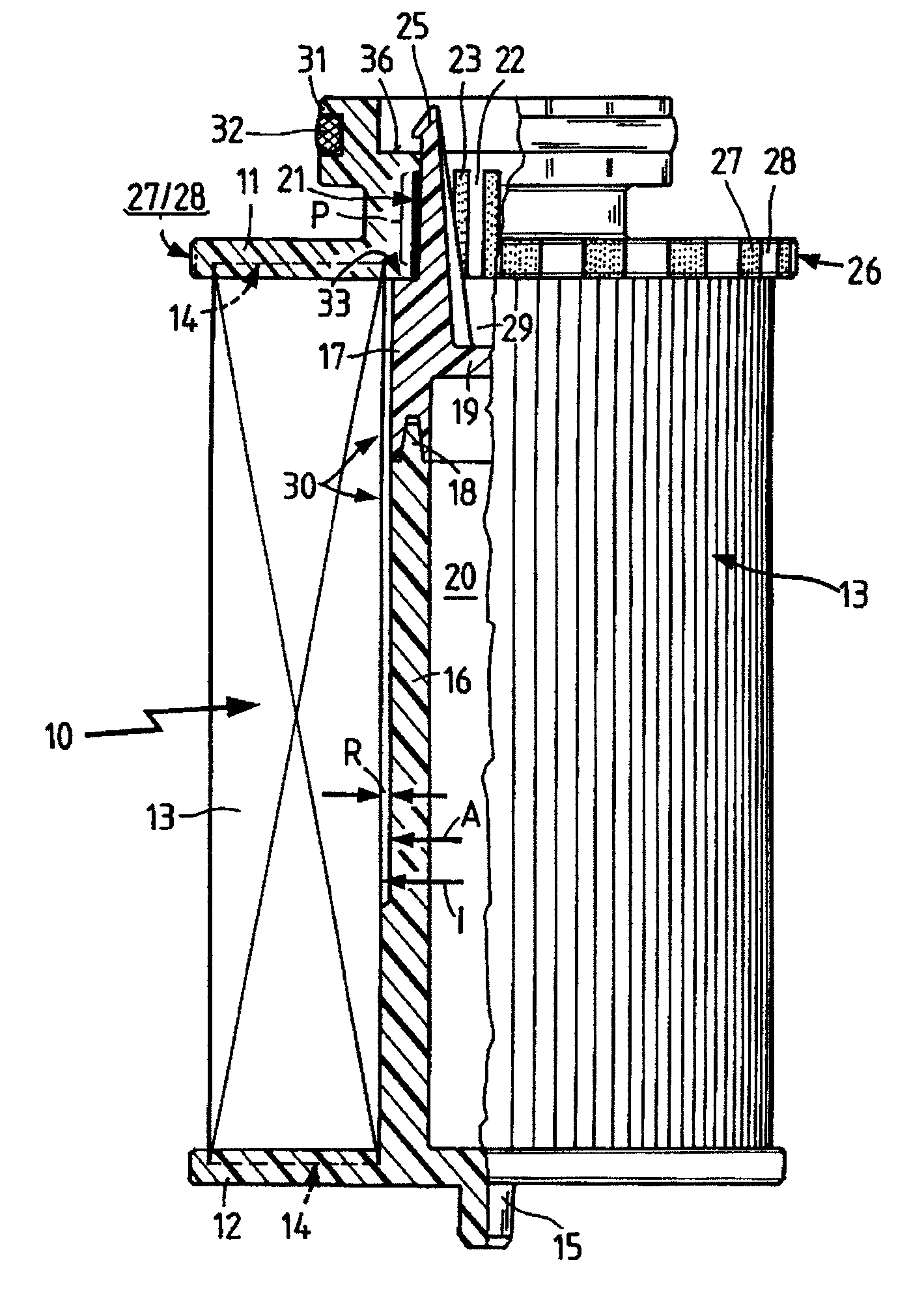
[0024]FIG. 1 shows a filter element 10 in a partial sectional view. The filter element 10 has a first end disk 11 and a second end disk 12, where the end disks 11, 12 are made of a thermoplastic material. A pleated filter medium 13 is situated with a seal between the end disks 11 and 12. The filter medium 13 is connected to the end disks 11, 12 by a butt-welding method, thus forming a connection zone 14.

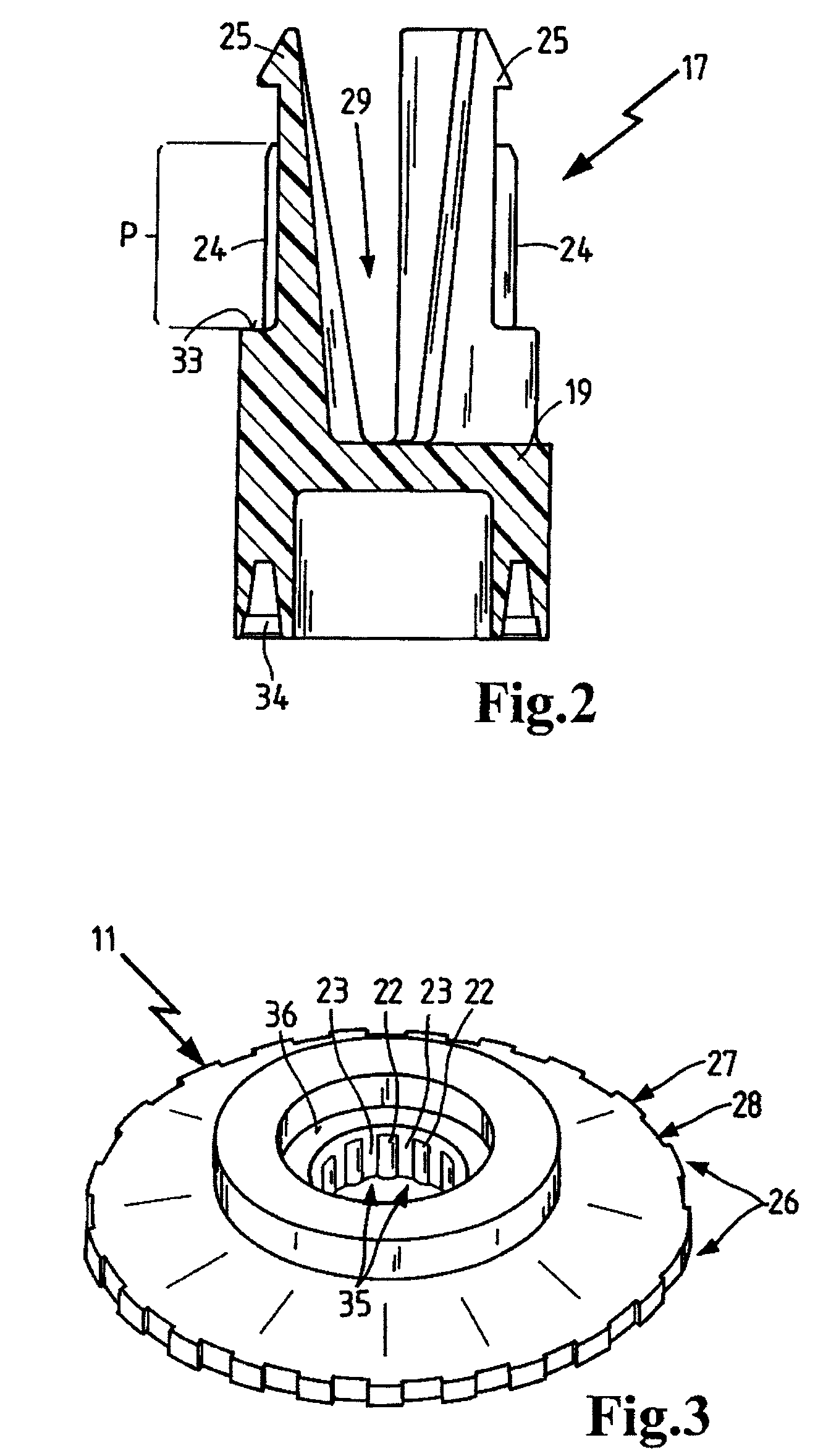
[0025]A centering pin 15 is integrally molded on the second end disks 12 and a pipe 16 is also integrally molded on the other side, these parts being made of the same plastic as the second end disk 12. The pipe 16 has an outside diameter “A” which is slightly smaller than an inside diameter I formed by the filter medium 13. The pipe 16 is connected with a seal to a connection 17, the connection being established by a spin welding method. To do so, the pipe 16 has a nose 18 which is partially melted in welding. In addition, parts of the connection 17 which are also made of a thermopla...


PUM

PropertyMeasurementUnit
Fractionaaaaaaaaaa
Fractionaaaaaaaaaa
Volumeaaaaaaaaaa

Abstract

A filter element (10) suitable for installation in a liquid filter for cleaning a freeze-endangered liquid; the liquid filter having a housing (37), composed of a housing pot (38), a housing cover (39), and a filter element (10) situated in the housing pot (38), with the housing cover (39) screwed onto the housing pot (38) in a sealed manner. The filter element (10) has a first end disk (11); a second end disk (12), and a filter medium (13) interposed between the end disks (11, 12). The end disks (11, 12) are mutually connected by a supporting element (30), which prevents radial relative movements between the end disks (11, 12). In the axial direction, the supporting element (30) has snap hooks (25) which connect the first end disk (11) undetachably to the second end disk (12). As a result of this connection, the second end disk (12) can be reliably removed from the housing pot (38) by pulling on the first end disk (11).

Description

BACKGROUND OF THE INVENTION[0001]This invention relates to a filter element for filtering a freeze-endangered liquid, such as a urea-water solution; to a liquid filter for filtering freeze-endangered liquids comprising a housing with an inlet and an outlet and containing a filter element according to the invention, and to a method for producing such a filter element.[0002]Published U.S. Patent Application No. US 2003 / 0209484 A1 describes a liquid filter for freeze-endangered liquids. The liquid filter has a housing which is closable by a filter cover. In the housing there is a filter element having a filter medium and end disks. Each end disk is attached to the filter medium by adhesive film. In addition, the end disks are joined together by a filler piece. The filler piece is therefore integrally molded onto a first end disk. On the end face opposite the end disk, the filler piece has a toothed area. The toothed area engages in an area located on the second end disk. Due to the int...

Claims


Application Information

Patent Timeline
IPC IPC(8): B01D35/30B01D27/00B01D29/11
CPCB01D29/111B01D29/21B01D29/902B01D2201/0415B01D2201/295B01D2201/4076B01D2201/4084B01D2201/403F01N2610/02F01N2610/1426
Inventor KRAMER, JOERG
Owner MANN HUMMEL GMBH
Why Eureka
Try Eureka