
Velocity detection, position detection and navigation system

a technology of velocity detection and position detection, applied in the direction of navigation instruments, position fixation, electrical/magnetic measurement arrangements, etc., can solve the problems of inability to accurately calculate the velocity of the mobile body, the sensor cannot be properly corrected, etc., and achieve the effect of high accuracy and accurate acceleration of the mobile body

Inactive Publication Date: 2009-03-17
SONY CORP
View PDF10 Cites 149 Cited by
  • Summary
  • Abstract
  • Description
  • Claims
  • Application Information

AI Technical Summary

Benefits of technology

This approach allows for high-accuracy velocity calculation and position estimation even without GPS signals, by accurately accounting for gravity acceleration components, thereby improving navigation system performance.

Problems solved by technology

Therefore, in a navigation system, there has been a problem that in the case where a gravity acceleration component varies when a GPS signal cannot be received, for example, as the case where the inclination of a slope varies in a tunnel, the detected value of an acceleration sensor cannot be properly corrected, therefore, the velocity of the mobile body cannot be correctly calculated.

Method used


Image

  • Velocity detection, position detection and navigation system
  • Velocity detection, position detection and navigation system
  • Velocity detection, position detection and navigation system

Examples


first embodiment

(1) First Embodiment

(1-1) Configuration of Navigation System

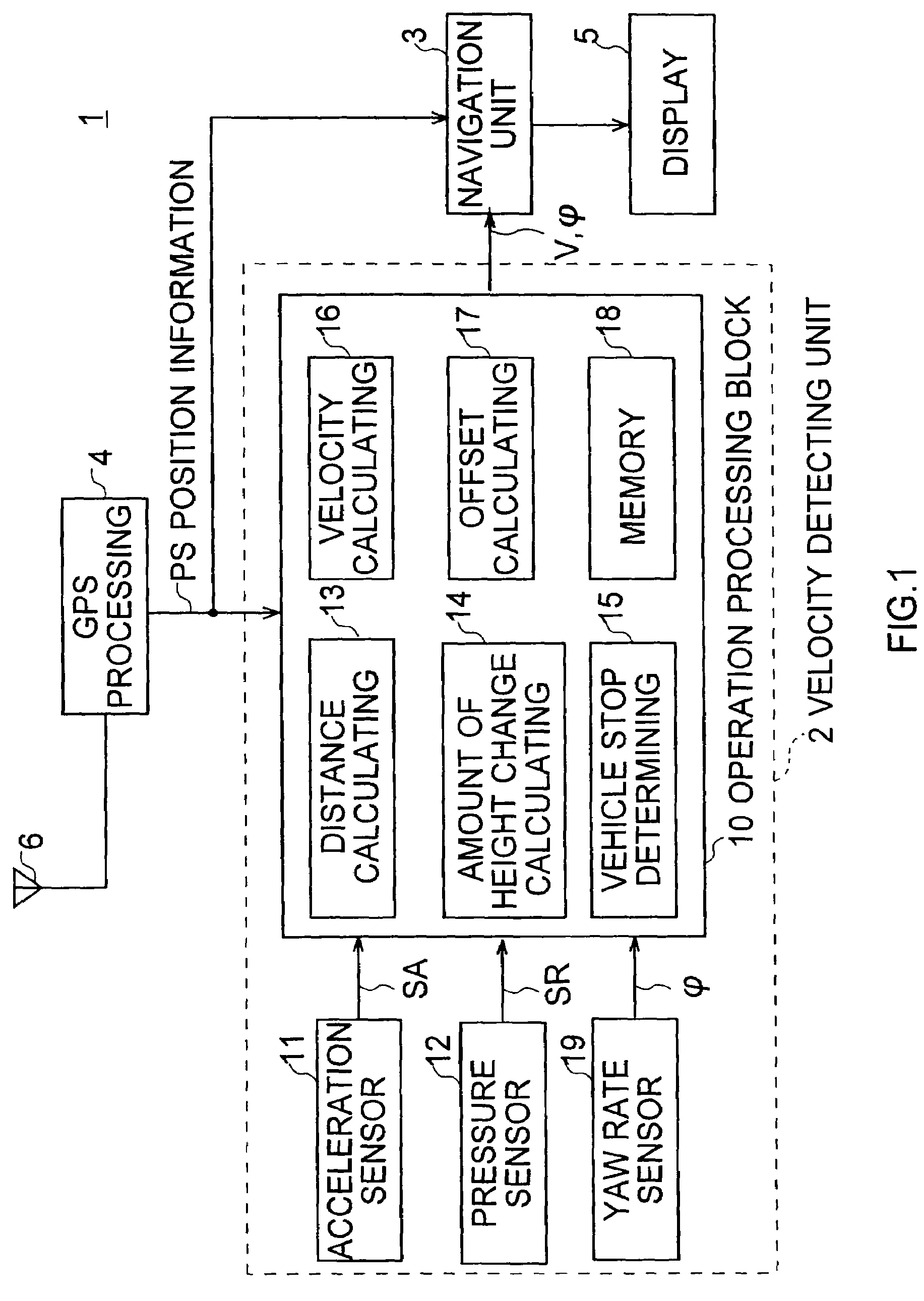
[0033]Referring to FIG. 1, a navigation system 1 is installed in a vehicle 100 (FIG. 2A) serving as a mobile body. The present position of the vehicle 100 is calculated by a Global Positioning System (GPS) processing section 4, based on a GPS signal received from a GPS satellite, display screen data is generated by superimposing a mark indicating the present position of the vehicle 100 or the like on predetermined map data by a navigation unit 3, and this is transmitted to a display section 5 and a display screen is displayed. Thereby, the user can see the position of the vehicle 100 on a map.

[0034]The GPS processing section 4 receives GPS signals from a plurality of GPS satellites (not shown) via a GPS antenna 6, generates position information PS by performing predetermined position calculating processing based on the GPS signals, and supplies this to an operation processing block 10 in a velocity detecting unit 2 and the ...

second embodiment

(2) Second Embodiment

(2-1) Configuration of Navigation System

[0140]As shown in FIG. 9 in that the same reference numerals are added to the corresponding parts in FIG. 1, a navigation system 20 in a second embodiment has a similar configuration to the navigation system 1 (FIG. 1) other than that a velocity detecting unit 21 is provided instead of the velocity detecting unit 2.

[0141]The velocity detecting unit 21 has an operation processing block 22 instead of the operation processing block 10 in the velocity detecting unit 2 (FIG. 1). In the operation processing block 22, in addition to the configuration of the operation processing block 10, an angular velocity correcting section 23 for performing the correcting processing of an angular velocity φ supplied from the yaw rate sensor 19 is provided.

[0142]As shown in FIG. 10A that corresponds to FIG. 2A, it is assumed that the vehicle 100 is running on a slope SL that has a slope angle θ to a horizontal plane HZ, in a forward direction F...


PUM


Abstract

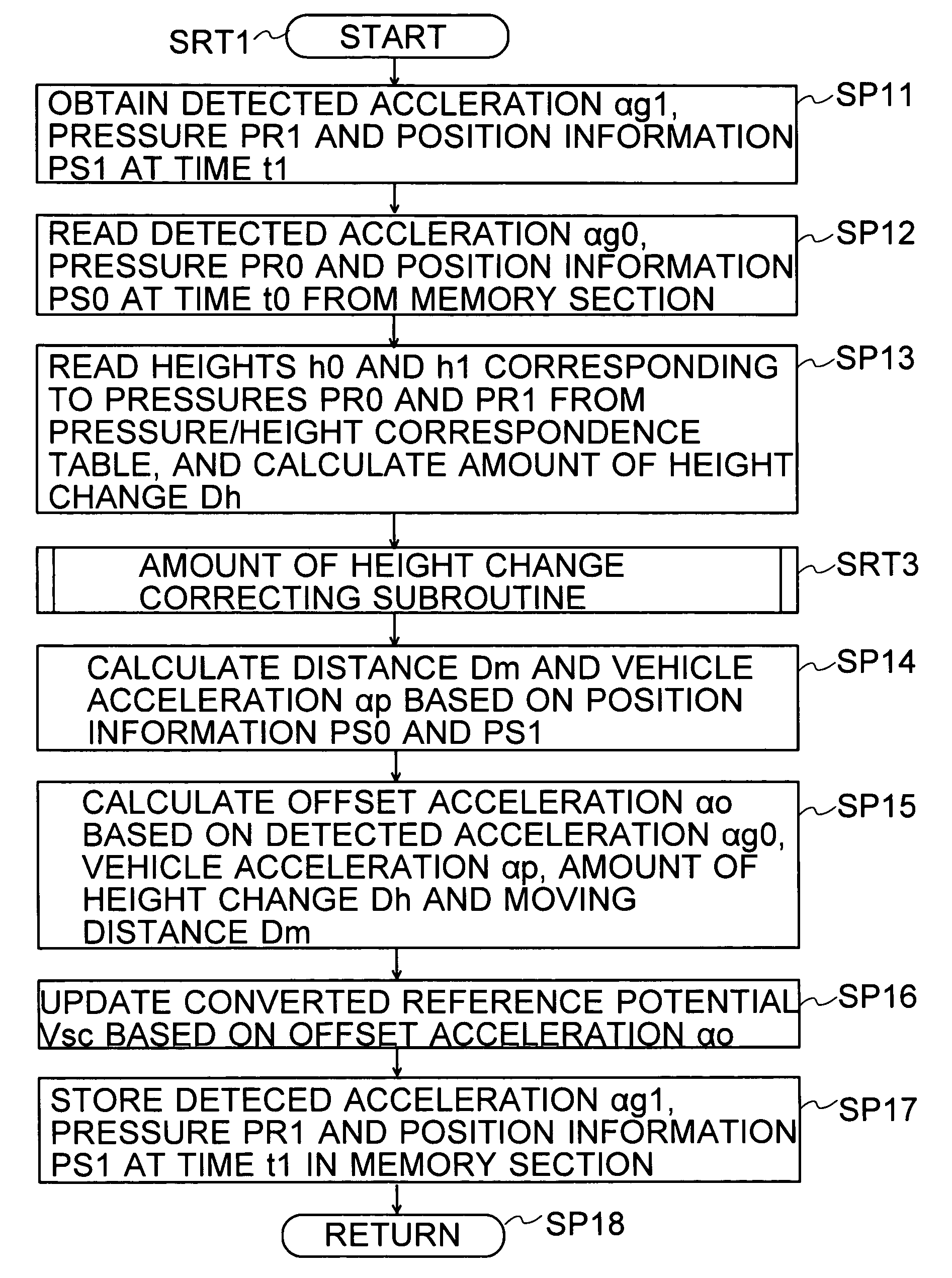
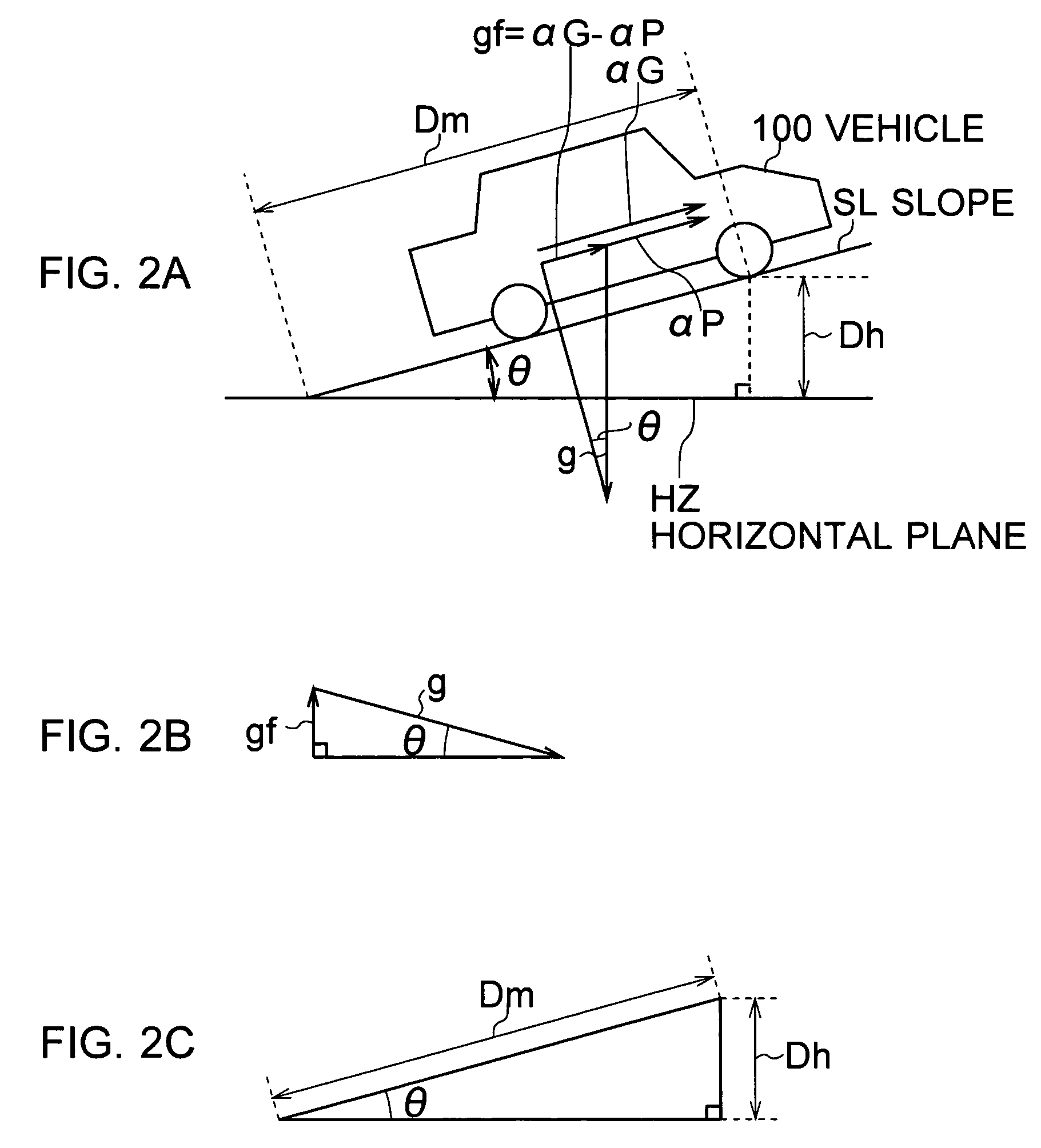
As an embodiment of the present invention, in a navigation system using an acceleration sensor, when position information cannot be obtained from a GPS processing section, a velocity detecting unit performs an operation using detected acceleration αG, a measurement time mt, a velocity V0 at a time t0, gravity acceleration g and an amount of height change Dh, according to Expression (11). By using the relationship among a gravity acceleration component gf, the gravity acceleration g, the amount of height change Dh and distance Dm shown in Expression (4), the gravity acceleration component gf can be offset by the amount of height change Dh. Therefore, velocity V can be calculated with high accuracy without receiving the effect of the gravity acceleration component gf.

Description

CROSS REFERENCE TO RELATED APPLICATION[0001]The present invention contains subject matter related to Japanese Patent Applications JP2005-258168 and 2006-203554 filed in the Japanese Patent Office on Sep. 6, 2005 and Jul. 26, 2006 respectively, the entire contents of which being incorporated herein by reference.BACKGROUND OF THE INVENTION[0002]1. Field of the Invention[0003]The present invention relates to a velocity detecting system, a velocity detecting method, a velocity detecting program, a position detecting system, a position detecting method and a position detecting program, and a navigation system, and is applicable to a navigation system to be installed in a mobile body, for example.[0004]2. Description of the Related Art[0005]Heretofore, a navigation system to be installed in a moving mobile body or the like in that the present position is calculated based on a GPS signal transmitted from a Global Positioning System (GPS) satellite, and the position and the forward directio...

Claims


Application Information

Patent Timeline
Patent Type & Authority Patents(United States)
IPC IPC(8): G06F19/00G01P3/50G01P7/00G09B29/00G09B29/10
CPCG01C21/28G01P7/00G01P3/62
Inventor OHKUBO, MASASHITAKAOKA, TOMOHISA
Owner SONY CORP
Learn More