
Low cost grease removal system

a grease removal and low cost technology, applied in the field of low cost assembly, can solve the problems of clogging of sewer system lines, messy and time-consuming servicing, and difficulty in servicing existing devices, and achieve the effect of convenient field servi

Active Publication Date: 2009-03-17
THERMACO INC
View PDF40 Cites 30 Cited by
  • Summary
  • Abstract
  • Description
  • Claims
  • Application Information

AI Technical Summary

Benefits of technology

The solution provides a cost-effective, easily maintainable system that efficiently removes oil, grease, and solid waste from effluent water, reducing sewer clogging and capital investment, while ensuring minimal downtime through replaceable parts and flexible installation options.

Problems solved by technology

Sewer system lines can become clogged from the oil and grease waste materials put into the sewer system from food handling facilities.
The existing devices may be difficult to service and are very often permanently installed at facility sites.
Because many of the parts are coated with oil and grease, servicing can be messy and time consuming.
In addition, these systems tend to be expensive and represent a significant capital investment.

Method used


Image

  • Low cost grease removal system
  • Low cost grease removal system
  • Low cost grease removal system

Examples


Embodiment Construction

[0025]In the following description, like reference characters designate like or corresponding parts throughout the several figures. It should be understood that the illustrations are for the purpose of describing preferred embodiments of the invention and are not intended to limit the invention thereto.

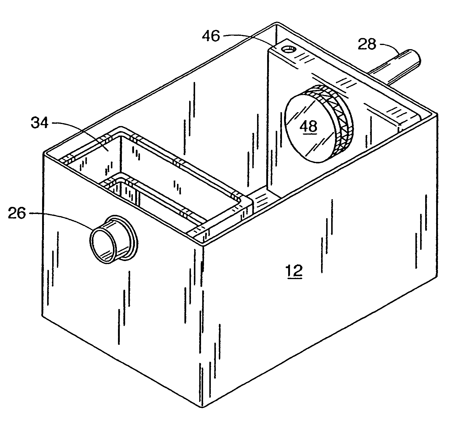
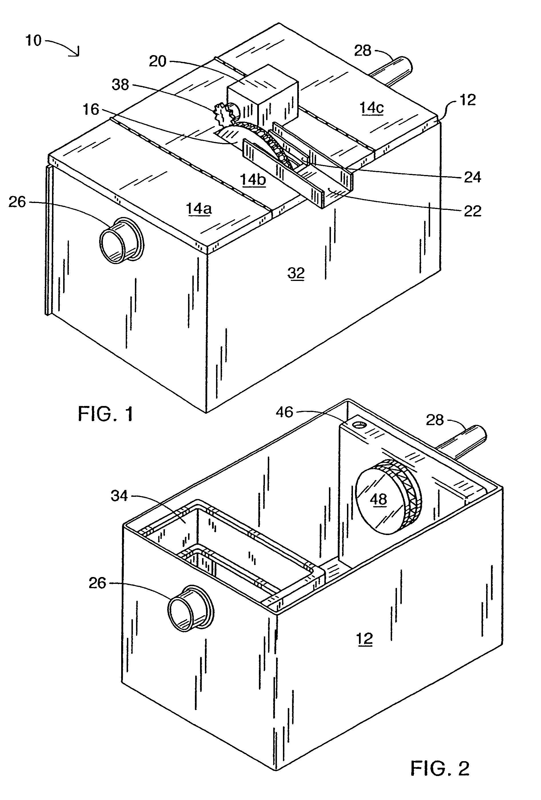
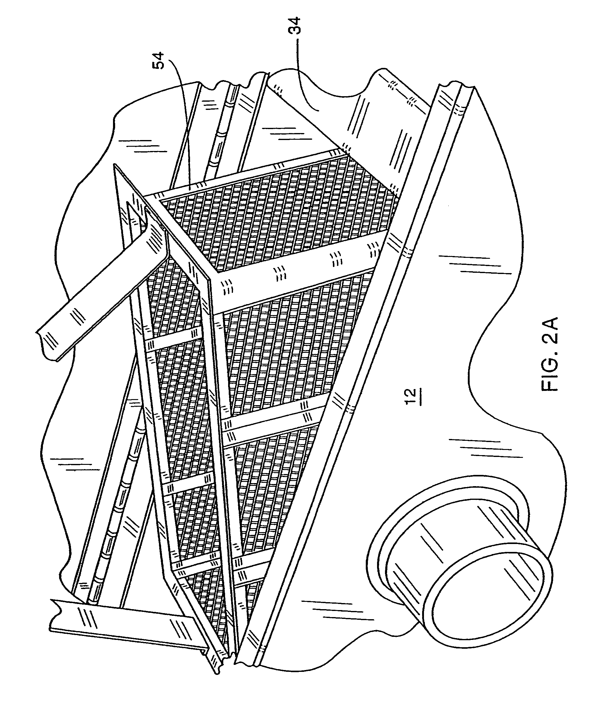
[0026]As best seen in FIG. 1, the oil, grease and solid removal assembly 10 includes a container 12 with sectional covers 14a, 14b, and 14c. In a preferred embodiment as seen in FIG. 1, the sectional covers are joined by hinges. Alternatively, they can be separate units, the view of FIG. 6 being an example. The assembly 10 has at least one rotatable disk 16 supported by the center sectional cover 14b. FIG. 1 also depicts the gear drive motor 20 and the trough 22 which are attached to the center sectional cover 14b. The container 12 also includes an inlet pipe 26 and an outlet pipe 28. The effluent water with waste materials enters through the inlet pipe 26, and the grey water, after o...


PUM

PropertyMeasurementUnit
forceaaaaaaaaaa
affinityaaaaaaaaaa
timeaaaaaaaaaa

Abstract

A low cost oil, grease removal assembly includes a rotomolded plastic container having an inlet and an outlet; a rotomolded plastic basket support located at the inlet inside the container; a rotomolded plastic outlet baffle located in the container at the outlet; a plurality of container cover sections including a first section to cover the basket support, a second container cover section having an oil, grease removal mechanism downstream of the basket support and upstream of the outlet baffle, and a third container cover section to cover the outlet baffle.

Description

[0001]This application is a division of utility application Ser. No. 10 / 767,145 filed Jan. 29, 2004, now U.S. Pat. No. 6,878,270, which is a division of utility application Ser. No. 10 / 161,814 filed Jun. 4, 2002 which issued Oct. 5, 2004 as U.S. Pat. No. 6,800,195.BACKGROUND OF THE INVENTION[0002]This invention relates to a low cost assembly for the removal and recovery of oil, grease and solid wastes found in drains or effluent discharge of restaurants, food processing, or like facilities, industrial plants, maintenance facilities, or other circumstances involving mixtures of oil, grease and solid waste material to be recovered or removed.DESCRIPTION OF PRIOR ART[0003]Oil, grease and solid waste contaminant removal or recovery systems are well known in the prior art. Over the past thirty years there has been a steady move towards requiring food handling facilities to have systems for servicing kitchen grease and solid waste bearing water flows. Sewer system lines can become clogged...

Claims


Application Information

Patent Timeline
Patent Type & Authority Patents(United States)
IPC IPC(8): B28B1/02B01D21/00B01D21/30B01D24/48B01D29/60B01D33/70B01D43/00B01D17/00C02F1/40
CPCB01D17/005B01D17/0202B01D17/0208B01D17/0214C02F1/40
Inventor BATTEN, WILLIAM C.KYLES, BRUCE W.
Owner THERMACO INC
Learn More