
Method for forming a semiconductor structure having nanometer line-width

a semiconductor structure and nanometer technology, applied in the field of forming a semiconductor structure, can solve the problems of difficult line-width control, high investment cost of hardware equipment, maintenance or materials, and the inability to form deep sub-micron or so-called nano-scale metal electrodes using conventional photolithography technology, etc., to achieve simple and cost-effective process, simple, cost-effective and competitive

Inactive Publication Date: 2009-03-10
NAT CHIAO TUNG UNIV
View PDF6 Cites 7 Cited by
  • Summary
  • Abstract
  • Description
  • Claims
  • Application Information

AI Technical Summary

Benefits of technology

"The present invention provides a method for making semiconductor structures with deep sub-micron line-width. The method involves sequentially forming layers of photoresist on a semiconductor substrate and patterning them using exposure and development processes. An anisotropic etching process is then performed to create an opening that defines the footprint of a metal electrode. This method is simple and cost-effective and can be used for high-frequency device fabrications. The technical effects of the invention are the ability to make complex semiconductor structures with nanometer gate lengths using conventional photolithography and anisotropic etching processes."

Problems solved by technology

However, forming deep sub-micron scale or so-called nano scale metal electrode using conventional photolithography technology is more challenging.
Nevertheless, the investment cost of the hardware equipment, maintenance or materials will be highly increased.
In addition, for EBL, the throughput is an issue that may become practical concern for the industrial mass production.
However, it is not easy to control the line-width and the overall process is quit complex.
Furthermore, it is not easy to realize T-type or Γ-type gate formation by this technique.
Partially development is not easy to control when compared to the selective development in the multi-layer resist structure.
Furthermore, it is not easy to realize T-type or Γ-type gate formation by this technique.
However, its application still would be quite limited.
Although Γ type gate with sub-micron line-width can be formed, the process steps are more complex.
The method disclosed in this invention is time-consuming and with higher production cost.

Method used


Image

  • Method for forming a semiconductor structure having nanometer line-width
  • Method for forming a semiconductor structure having nanometer line-width
  • Method for forming a semiconductor structure having nanometer line-width

Examples


Embodiment Construction

[0029]The following is a description of the present invention and the invention will firstly be described with reference to one exemplary structure. Some variations will then be described as well as the advantages of the present invention. A preferred method of fabrication will then be discussed; also, an alternate, asymmetric embodiment will then be described along with the variations in the process flow.

[0030]The technology provided by the invention is for solving the issues met in the fabrication of deep sub-micron or nano scale line-width in the semiconductor industry. The invention only needs conventional semiconductor equipments for use, such as I-line stepper or DUV contact aligner, in order to achieve the purpose for forming patterns with small feature size via a relatively simple and cost-effective method. Therefore the methods disclosed in this invention are suitable for mass production in the industrial for the manufacture of deep sub-micron or nano scale high-speed elect...


PUM


Abstract

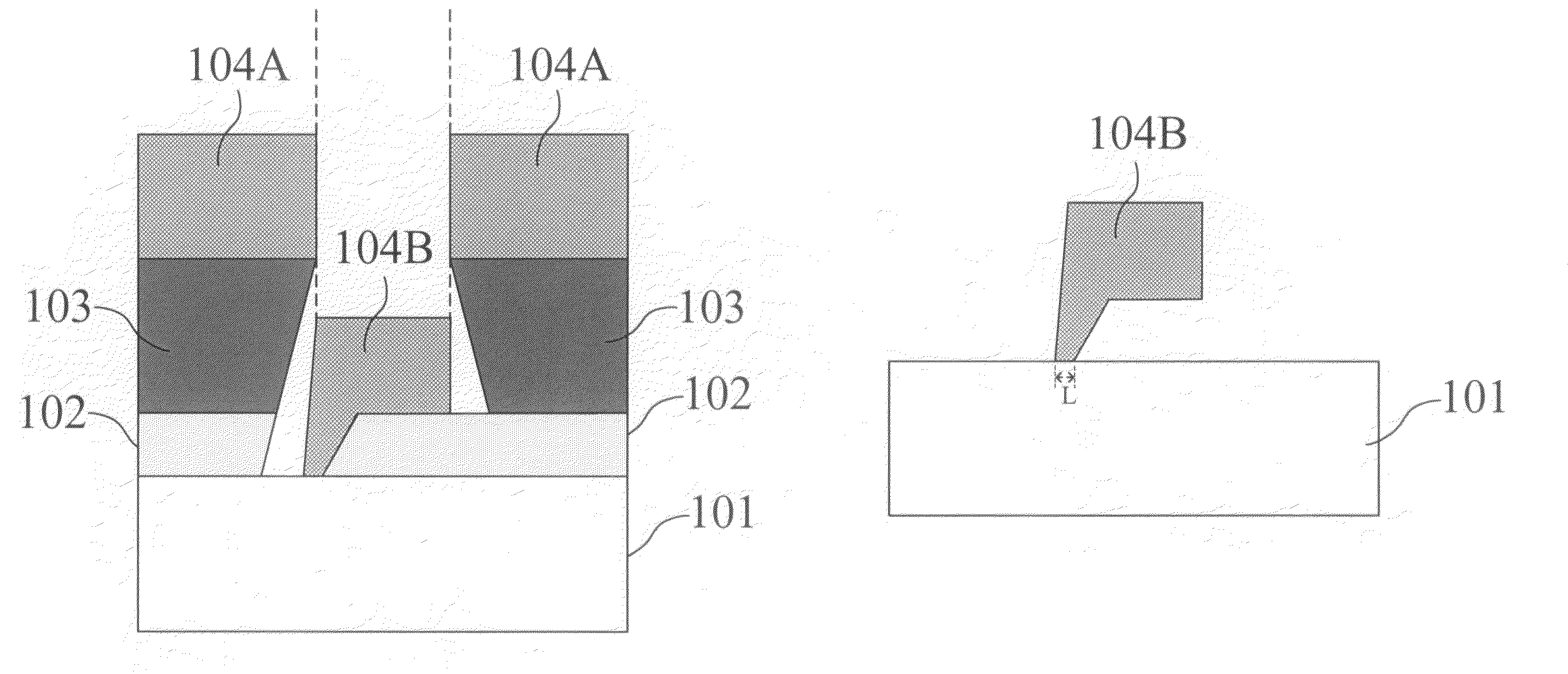
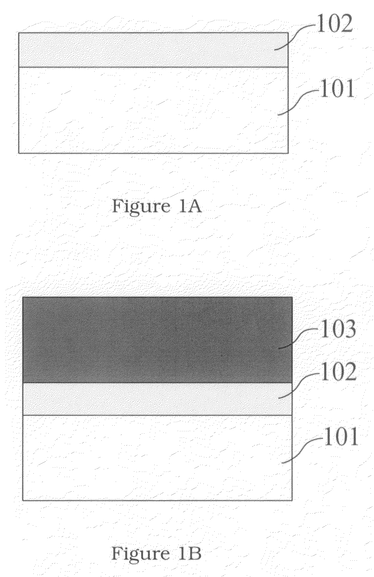
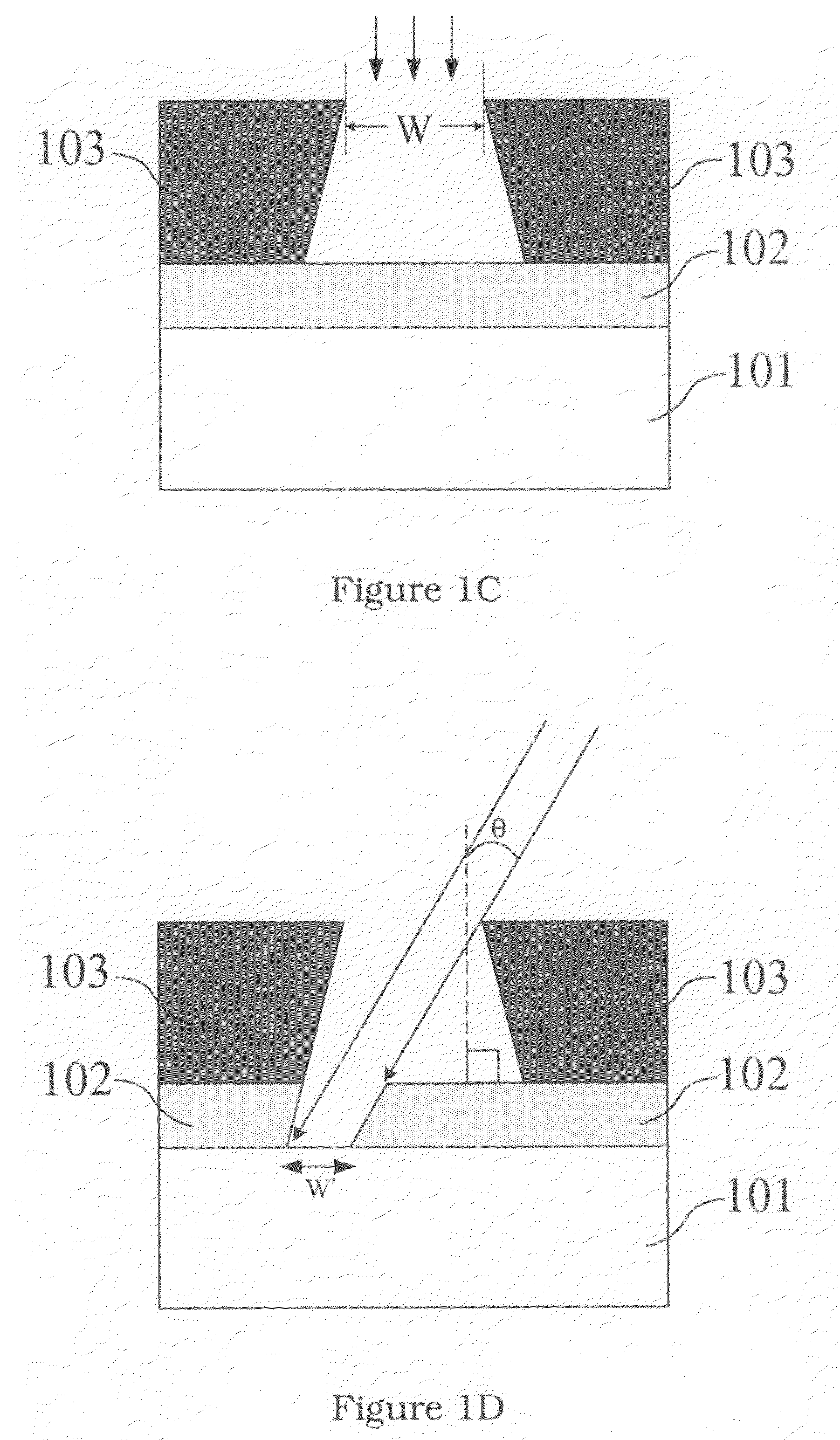
A method for forming a semiconductor structure having a deep sub-micron or nano scale line-width is disclosed. Structure consisting of multiple photoresist layers is first formed on the substrate, then patterned using adequate exposure energy and development condition so that the bottom photoresist layer is not developed while the first under-cut resist groove is formed on top of the bottom photoresist layer. Anisotropic etching is then performed at a proper angle to the normal of the substrate surface, and a second resist groove is formed by the anisotropic etching. Finally, the metal evaporation process and the lift-off process are carried out and the Γ-shaped metal gate with nano scale line-width can be formed.

Description

BACKGROUND OF THE INVENTION[0001]1. Field of the Invention[0002]The invention relates to forming a semiconductor structure, more particularly for forming a semiconductor structure having a deep sub-micron line-width.[0003]2. Description of the Prior Art[0004]The semiconductor technology right now is still highly researched and developed to improve the current semiconductor device performance; also, deep sub-micron scale or so-called nano-scale line-width metal electrode technology is a key technology for semiconductor device manufacturing and could become much more important when the device dimension continues being downscaled. The previous sub-micron scale line-width metal electrode technology all can be carried out by the photolithography technology. However, forming deep sub-micron scale or so-called nano scale metal electrode using conventional photolithography technology is more challenging.[0005]At the present day, for deep sub-micron technology development, optical lithograph...

Claims


Application Information

Patent Timeline
Patent Type & Authority Patents(United States)
IPC IPC(8): H01L21/302H01L21/461
CPCH01L21/0272H01L29/42312
Inventor CHEN, SZU-HUNGLIEN, YI-CHUNGCHANG, YI EDWARD
Owner NAT CHIAO TUNG UNIV
Learn More