Apparatus and method for optical switching with liquid crystals and birefringent wedges
a technology of liquid crystals and wedges, applied in the field of optical switching, can solve the problems of increasing the coupling loss to an output port, unable to achieve the promise, and creating significant challenges for control and long-term stability
- Summary
- Abstract
- Description
- Claims
- Application Information
AI Technical Summary
Benefits of technology
Problems solved by technology
Method used
Image
Examples
first embodiment
[0063]FIG. 9 illustrates the invention. It is a 1×4 optical routing switch for a fiber optic system. It is not wavelength specific. Light exits the input fiber 902 and passes through a collimator / BD / retarder coupling assembly 904. The two parallel beams then pass through the LC / wedge switching assembly 906 and through the action of the switch the beams are deflected to 1 of 4 output ports 908. Each output port contains a retarder / BD / collimator assembly 910 for coupling to that port's output fiber. The switch assembly is for concreteness here assumed to have its LC and wedge configuration according to the bifurcation diagram of FIG. 7b. With reference to FIG. 7b, it is clear that two of the beams output from the switch assembly have their polarizations orthogonal to the input polarization. For these two beams, which correspond to output ports 1912 and 3914 in FIG. 9, the half wave retarders 916 and 918 in the coupling assembly must be moved, as shown in the figure, to the opposite be...
second embodiment
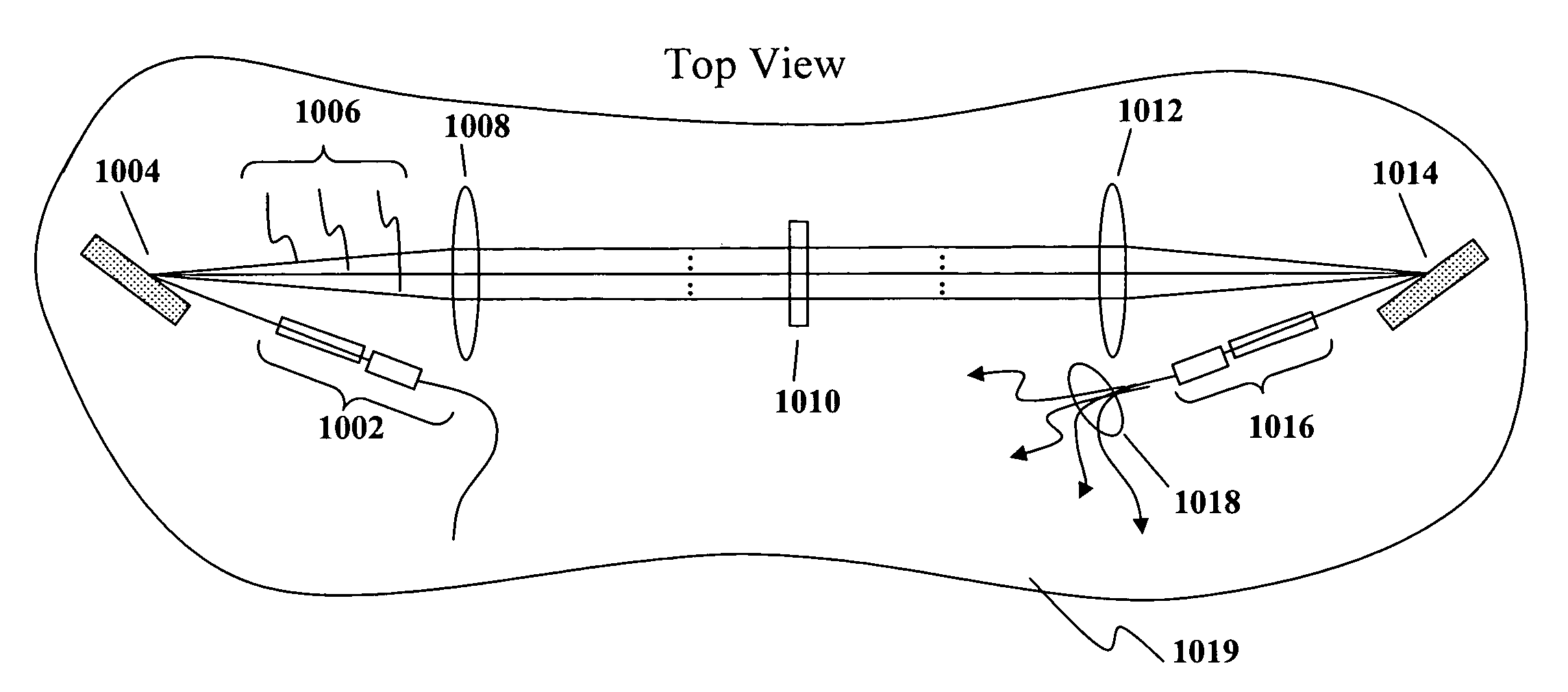
[0064]FIG. 10 illustrates a second embodiment which functions as a 1×4 wavelength switch for a WDM fiber optic network. With reference to FIG. 10a, this device comprises (1) an input fiber coupling assembly 1002 (i.e. collimator / BD / waveplate) which provides two parallel beams of identical polarization, (2) a dispersive means 1004 (e.g., a grating) which takes these polarized beams and separates them into their component wavelengths 1006, (3) a means with optical power 1008 (e.g. a lens) in the path of the dispersed beams which serves two functions: it converts the diverging dispersed beams into an array of parallel beams and focuses the beams on the switching assembly, (4) an LC / wedge switching assembly 1010, (5) a second means with optical power 1012 (lens) that performs the inverse functions of the first means with optical power, collimating the dispersed beams and focusing these beams to the same point on (6) a second dispersive means 1014 (e.g., a second grating) which combines ...
third embodiment
[0068]FIG. 11 is a 1×4 wavelength-selective switch that contains a reflective means, thereby eliminating the second means with optical power as well as the second dispersive means of the previous embodiment. With reference to FIG. 11a, light containing N discrete wavelengths exits the input fiber 1102, passing first through an input coupling assembly 1104 which produces two parallel beams with the same polarization. A dispersive means 1108 (here a diffraction grating) separates the beams into N pairs of beams 1110, one pair for each component wavelength. A means with optical power 1112 (here a convex spherical lens) focuses the separate beams onto the LC switch assembly 1114. A reflective means after the switch assembly then returns the light in reverse order back through the LC assembly, the means with optical power, and the dispersive means after which it is coupled back to 1 of 4 four output ports via the coupling array. A detail of the switching assembly is illustrated in FIG. 1...
PUM
 Abstract
Description
Claims
Application Information
 - R&D
- Intellectual Property
- Life Sciences
- Materials
- Tech Scout
- Unparalleled Data Quality
- Higher Quality Content
- 60% Fewer Hallucinations
Browse by: Latest US Patents, China's latest patents, Technical Efficacy Thesaurus, Application Domain, Technology Topic, Popular Technical Reports.
© 2025 PatSnap. All rights reserved.Legal|Privacy policy|Modern Slavery Act Transparency Statement|Sitemap|About US| Contact US: help@patsnap.com


