
Field probe from the angular response of a rigid body

a rigid body and field probe technology, applied in the field ofradar test ranges, can solve the problems of placing additional cost burdens on test programs and actual measurements remain unquantified

Inactive Publication Date: 2009-03-03
THE BOEING CO
View PDF7 Cites 10 Cited by
  • Summary
  • Abstract
  • Description
  • Claims
  • Application Information

AI Technical Summary

Problems solved by technology

Unfortunately, the time and equipment required for field probing can places additional cost burdens on test programs.
Without a probe of the test range, actual measurements remain unquantified.

Method used


Image

  • Field probe from the angular response of a rigid body
  • Field probe from the angular response of a rigid body
  • Field probe from the angular response of a rigid body

Examples


example

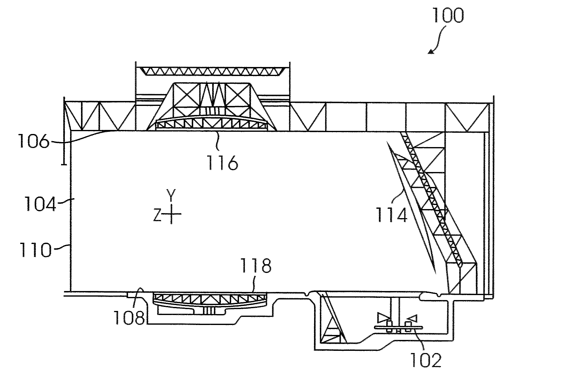
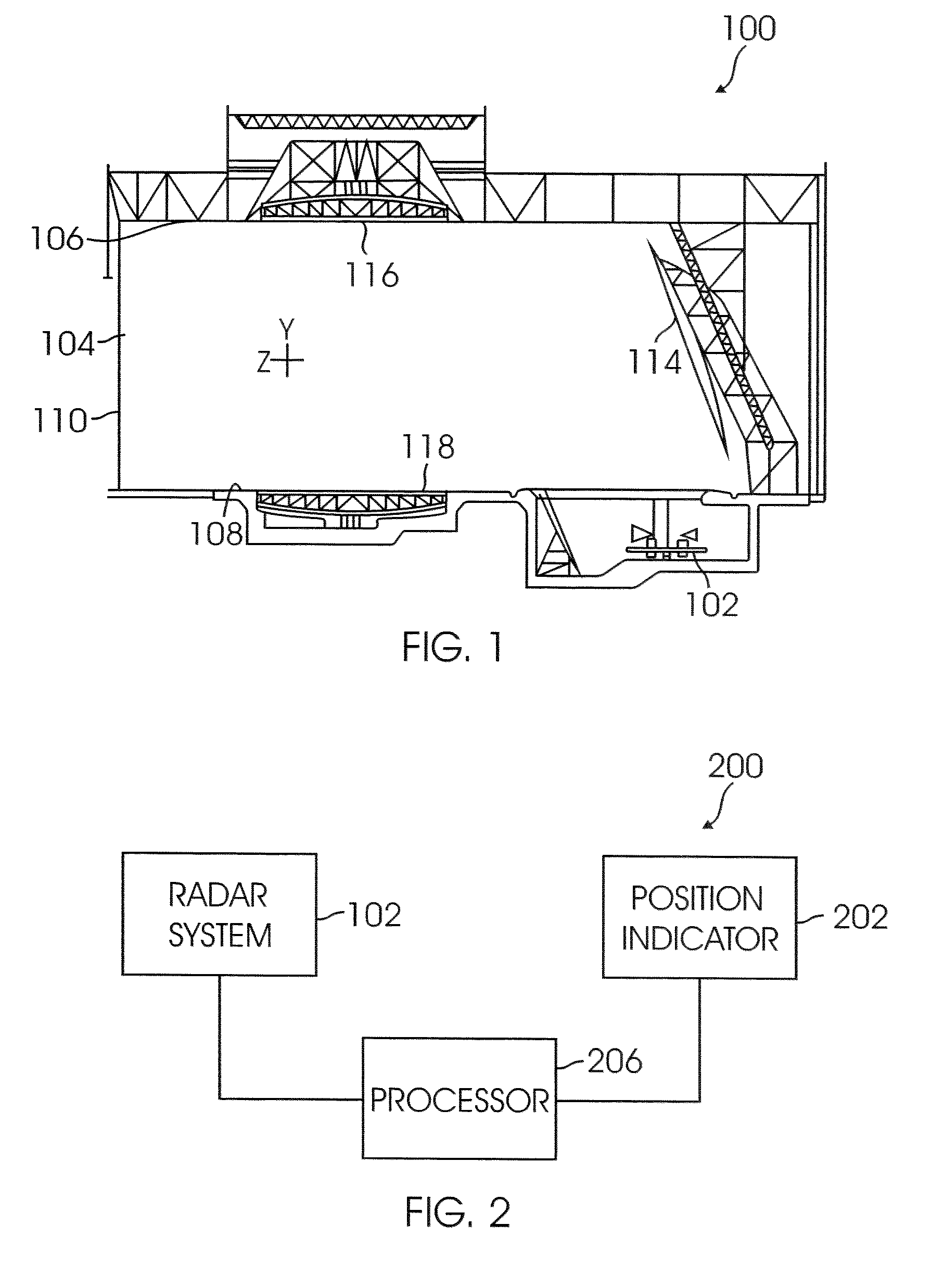
[0043]In the following example, 1.74-inch diameter rod, made of galvanized thin-wall steel was used as rigid body 300. The rod measured 60 feet and was suspended in a horizontal plane from upper turntable (UTT) 116. When UTT 116 is rotated, the angle between rigid body 300 and the direction of arrival of the incident radar wave is changed, thereby varying radar response of rigid body 300. An example of the angular radar response in a test range is as shown in FIG. 5 for a frequency of 2.4 GHz and vertical transmit / vertical receive (VV) polarization. The angular radar response (echo) is charted in logarithmic scale in decibels-square meter (dBsm). FIG. 5 shows the typical azimuth dependence of the radar echoes at 2.4 GHz from the 60-foot long rod. Radar response (echo) is strongest within a narrow angular range. The independent variable is the UTT-angle, which within a small inclination (.+−.10.degree.) from the vertical plane normal to the incident wave direction, is linearly propor...


PUM


Abstract

Probing incident radar fields in a target test zone of a RCS test facility by exploiting angular radar response of a long and uniform rigid body supported horizontally across or vertically through the test zone. The rigid body is free to rotate about the broadside condition. Thus, the angle of the rigid body is gradually changed with respect to the direction of arrival of the incident wave. Radar echo from the rigid body is measured as a function of the rigid body angle. The data is then processed to yield a profile of the incident wave intensity along the rigid body. By varying the azimuth angle continuously while recording radar data, the data may be processed by the fast Fourier transform (FFT) algorithm to yield a profile of the incident wave intensity along the rigid body.

Description

BACKGROUND[0001]1. Field of the Invention[0002]This invention relates generally to test ranges and, more specifically, to radar test ranges.[0003]2. Related Art[0004]A radar cross-section (RCS) test range is a facility for measuring radar scattering properties of test objects, such as aircraft and missiles. Radar cross-section test ranges have been built to provide a “quiet” test zone for measuring radar signature of a test object. “Quiet” means that the incident radar wave in the test zone is acceptably free from undesired interference or unwanted reflections from elsewhere in or on the test range.[0005]Operating conditions of a test range can change over time, with changes of equipment, and with arrangement of radar absorbers. Thus, it is considered good practice to probe the test zone of the range at regular intervals to ensure that radar fields within the test zone behave as expected. Unfortunately, the time and equipment required for field probing can places additional cost bur...

Claims


Application Information

Patent Timeline
Patent Type & Authority Patents(United States)
IPC IPC(8): G01S7/40G01S13/00
CPCG01S7/40G01S7/41
Inventor WEI, PAX S. P.REED, ANTHONY W.ERICKSEN, CRAIG N.DOTY, JAMES D.SCHUESSLER, ROBERT K.
Owner THE BOEING CO
Learn More