
Proximity radar antenna co-located with GPS DRA fuze

a technology of proximity radar and gps dra fuze, which is applied in the direction of polarised antenna unit combinations, instruments, and reradiation, can solve the problems of performance degradation of gps antenna configurations on the side of fuzes, and achieve the effect of reducing the total amount of space occupied by antennas and optimizing gps and proximity radar operations

Active Publication Date: 2009-03-03
ROCKWELL COLLINS INC
View PDF21 Cites 35 Cited by
  • Summary
  • Abstract
  • Description
  • Claims
  • Application Information

AI Technical Summary

Benefits of technology

[0007]The present invention provides a nose-mounted fuze antenna capable of optimal GPS and proximity radar operations. Due to the HE11δ mode structure of the GPS DRA fuze, an E-field null exists at the center of the DRA dielectric cone, allowing for benign insertion of proximity radar antenna while keeping the GPS DRA fuze and the proximity radar electrically isolated from each other. The high dielectric constant of DRA dielectric cone permits the GPS DRA fuze to operate in the L1 frequency and the electrically shortened proximity radar antenna to resonate in the C-Band within a small form factor. The GPS DRA fuze maintains a forward-looking CP (circular polarization) pattern while proximity antenna maintains a desirable LP (linear polarization) monopole pattern. Nesting the proximity radar antenna inside the GPS DRA fuze allows both antennas to be mounted on the fuze nose while simultaneously reducing the total amount of space occupied by antennas.

Problems solved by technology

However, due to space and interference considerations, the proximity antenna is typically mounted on the fuse tip.
Fuze application antenna configurations with either GPS antennas located on the side of the fuze are subject to performance degradation such as carrier-phase roll-up.

Method used


Image

  • Proximity radar antenna co-located with GPS DRA fuze
  • Proximity radar antenna co-located with GPS DRA fuze
  • Proximity radar antenna co-located with GPS DRA fuze

Examples


Embodiment Construction

[0014]Reference will now be made in detail to exemplary embodiments of the invention, examples of which are illustrated in the accompanying drawings.

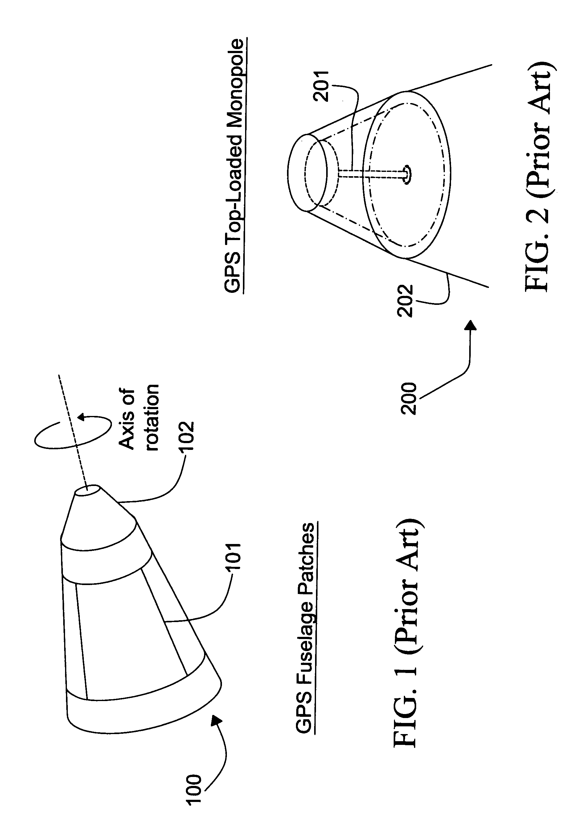
[0015]Referring generally to FIG. 1; the GPS (Global Positioning System) and proximity radar antenna configuration of a fuze 100, as is known in the art, is illustrated. Proximity radar antenna 102 is located in the nose of the fuze 100. GPS antenna patches 101 are located on the side / fuselage of the fuze 100. In this configuration, the performance of proximity radar antenna 102 is optimal. However, in this configuration, GPS antenna patches 101 experience performance degradation such as carrier-phase roll-up.

[0016]Referring now to FIG. 2; the GPS and proximity radar antenna configuration of a fuze 200, as is known in the art, is illustrated. GPS top-loaded monopole 201 is located in the nose of the fuze 200. Proximity radar antenna 202 is located on the side / fuselage of the fuze 200. In order to realize azimuthal symmetry for the proxi...


PUM


Abstract

The present invention is directed to a fuze application capable of GPS (Global Positioning System) and proximity radar functionality by co-locating a proximity radar antenna with a GPS DRA (Dielectric Resonator Antenna) fuze. The GPS DRA fuze has a HE11δ mode structure resulting in an E-field null at the center. The monopole proximity radar antenna is mounted in the E-field null center and is thus electrically isolated from the GPS DRA fuze. The high dielectric constant permits the GPS DRA fuze to operate in the L1 frequency and the electrically shortened proximity radar antenna to resonate in the C-Band within a small form factor. The GPS DRA fuze maintains a forward-looking CP (circular polarization) pattern while proximity antenna maintains a desirable monopole pattern. Nesting allows mounting of both GPS and proximity radar antennas on the fuze nose while reducing the total space occupied.

Description

FIELD OF THE INVENTION[0001]The present invention relates generally to fuze applications and more particularly to a proximity radar antenna co-located with a GPS (Global Positioning System) DRA (Dielectric Resonator Antenna) fuze.BACKGROUND OF THE INVENTION[0002]A fuze is a mechanical and / or electrical device typically located at the leading end of a delivery system, such as an artillery shell, designed to control detonation. Delivery systems, such as artillery shells, utilize various technologies to accurately control detonation in order to maximize damage to the target while minimizing collateral damage. Fuze applications may utilize GPS (Global Positioning System) functionality for flight and proximity radar functionality for descent. GPS and proximity radar provide fuze applications with improved accuracy and detonation control, thus reducing collateral damage.[0003]Typically, fuze applications have either GPS antennas or proximity radar antennas located on the tip of the fuze. ...

Claims


Application Information

Patent Timeline
Patent Type & Authority Patents(United States)
IPC IPC(8): F41G7/28F42B15/01F42C13/04G01S13/88H01Q1/28H04B7/185G01S19/36
CPCF41G7/346F42C19/00G01S19/36H01Q1/281H01Q1/288H01Q9/0492H01Q9/30H01Q21/24
Inventor PAULSEN, LEE M.WEST, JAMES B.
Owner ROCKWELL COLLINS INC
Learn More