Controller for an electric four-wheel-drive vehicle
a four-wheel drive, controller technology, applied in electric propulsion mounting, battery/cell propulsion, transportation and packaging, etc., can solve the problems of excessive power as motor torque, vehicle behavior change, and generated torque is essentially more than adequate for a vehicle run, so as to reduce torque changes and consume excessive power
- Summary
- Abstract
- Description
- Claims
- Application Information
AI Technical Summary
Benefits of technology
Problems solved by technology
Method used
Image
Examples
first embodiment
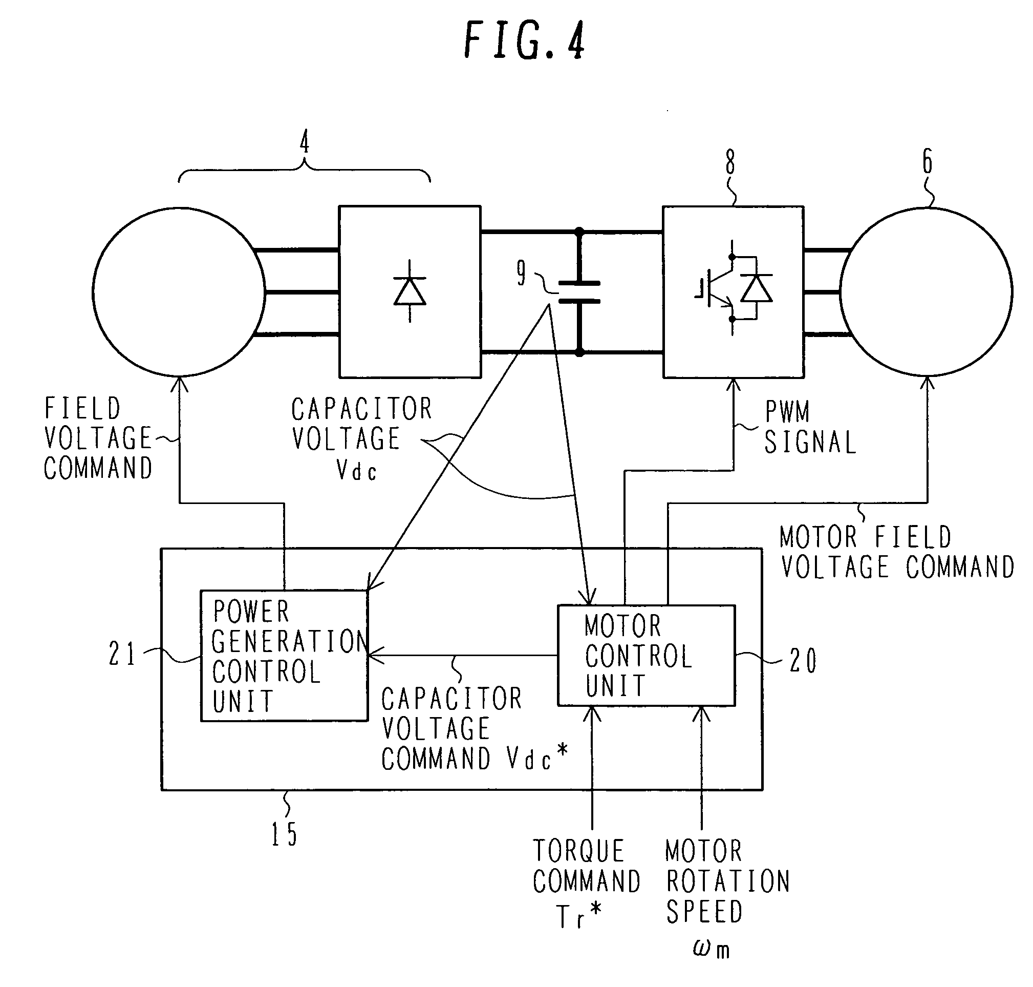
[0034]A controller for an electric four-wheel-drive vehicle according to the present invention will now be described with reference to FIGS. 1 to 6.
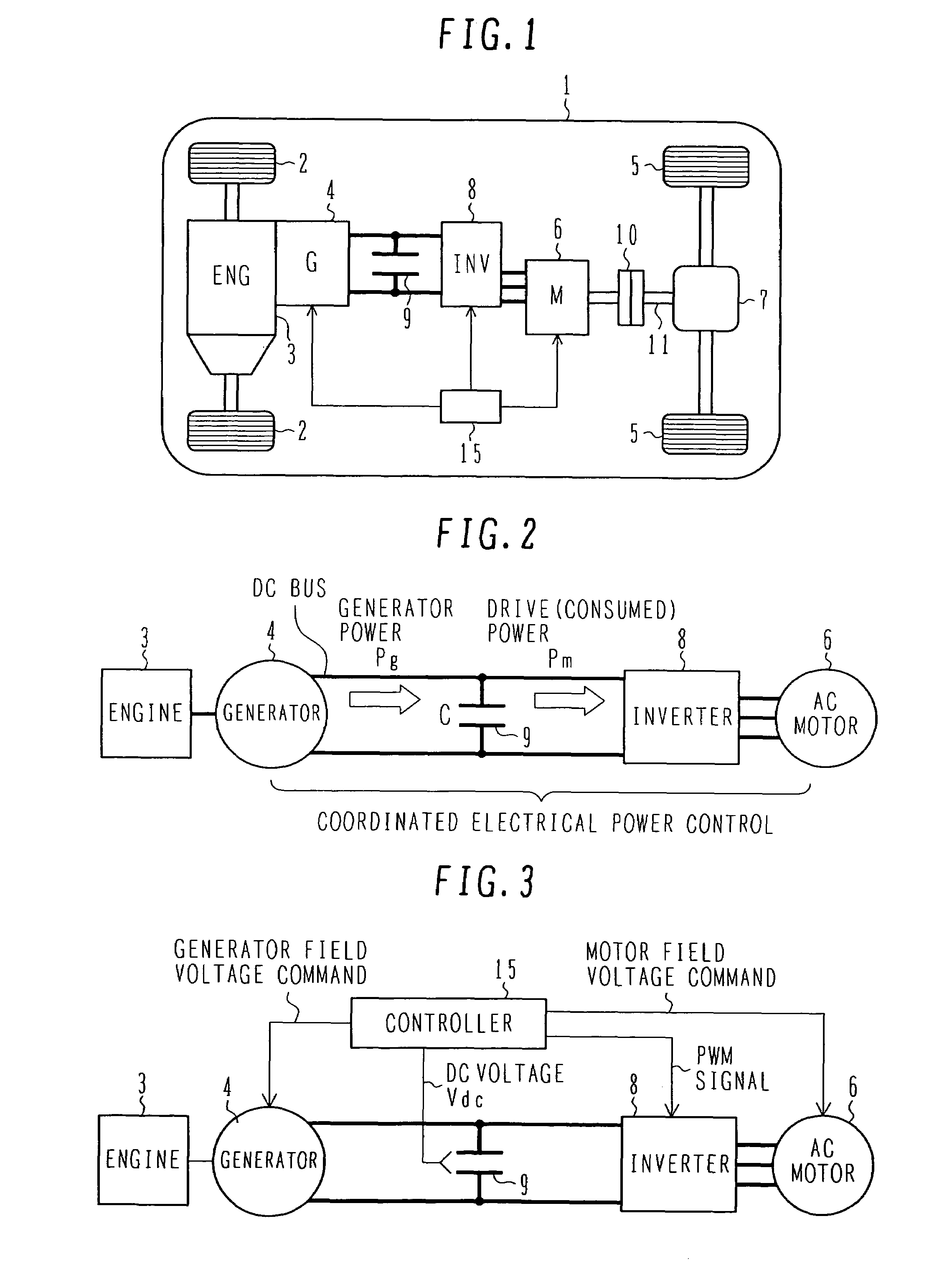
[0035]First of all, the system configuration for an electric four-wheel-drive vehicle to which the controller according to the first embodiment of the present invention is applied will be described with reference to FIG. 1.
[0036]FIG. 1 is a system configuration diagram illustrating the electric four-wheel-drive vehicle to which the controller according to the first embodiment of the present invention is applied.
[0037]In the electric four-wheel-drive vehicle 1, a dedicated generator 4 is connected to an engine 3 that drives front wheels 2. An AC motor 6 generates motive energy on the basis of power generated by the generator 4. The motive energy generated by the AC motor 6 drives rear wheels 5. This motive energy is distributed to the right and left by a differential gear unit 7 and transmitted to the rear wheels 5.
[0038]A 4WD clutch 10, ...
second embodiment
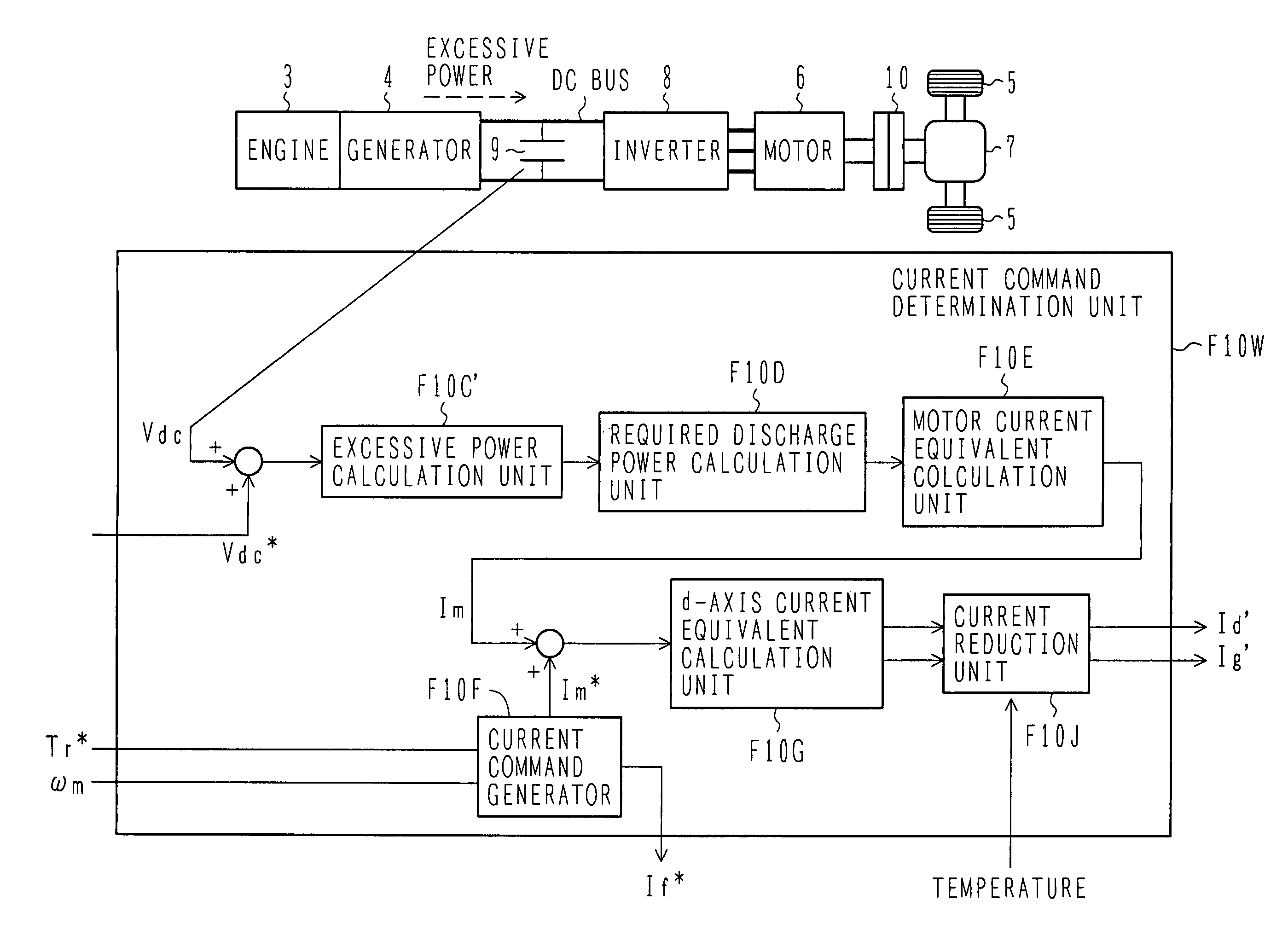
[0084]FIG. 7 is a block diagram illustrating the configuration of a current command determination unit that is included in the motor control unit for use in the controller according to the present invention. Elements shown in FIGS. 6 and 7 are designated by the same reference numerals when they are identical with each other.
[0085]The embodiment shown in FIG. 6 calculates the generated power Pg and input power Pm from respective physical quantities. However, the use of such a calculation method may affect the calculation load on the controller 15. Therefore, the present embodiment performs a simplified, proper process. The process that the present embodiment performs to consume the excessive power is basically based on the voltage of the capacitor 9.
[0086]The current command determination unit F10X includes an excessive power calculation unit F10C′, the required discharge power calculation unit F10D, the motor current equivalent calculation unit F10E, the current command calculation ...
third embodiment
[0100]FIG. 8 is a block diagram illustrating the configuration of a current command determination unit that is included in the motor control unit for use in the controller according to the present invention. Elements shown in FIGS. 6 and 8 are designated by the same reference numerals when they are identical with each other.
[0101]The current command determination unit F10Y included in the present embodiment differs from the current command determination unit F10 shown in FIG. 6 in that a current limiting unit F10H is furnished and positioned after the current equivalent calculation unit F10G. In the examples shown in FIGS. 6 and 7, the d-axis current is increased to increase the motor loss. However, the d-axis current cannot be allowed to flow in excess of the maximum allowable current for the inverter and motor. In the present embodiment, therefore, the current limiting unit F10H is furnished to limit the motor loss, which should be increased, when the motor current is smaller than...
PUM
 Abstract
Description
Claims
Application Information
 - R&D
- Intellectual Property
- Life Sciences
- Materials
- Tech Scout
- Unparalleled Data Quality
- Higher Quality Content
- 60% Fewer Hallucinations
Browse by: Latest US Patents, China's latest patents, Technical Efficacy Thesaurus, Application Domain, Technology Topic, Popular Technical Reports.
© 2025 PatSnap. All rights reserved.Legal|Privacy policy|Modern Slavery Act Transparency Statement|Sitemap|About US| Contact US: help@patsnap.com


