
Fluid conduit connector apparatus

a technology of conduit connectors and connectors, which is applied in the direction of couplings, discharge methods of containers, drawing-off water installations, etc., can solve the problems of emboli forming potentially life-threatening blockages in main pulmonary arteries, affecting the comfort and compliance of patients, and affecting the flow rate of blood, so as to facilitate the coupling of the removable portion, reduce bulk, and improve comfort and complian

Active Publication Date: 2009-02-17
KPR U S LLC
View PDF107 Cites 56 Cited by
  • Summary
  • Abstract
  • Description
  • Claims
  • Application Information

AI Technical Summary

Benefits of technology

The patent text describes a compression apparatus that includes a removable portion of a compression sleeve and a valve connector for supplying fluid to the apparatus. The valve connector allows for uninterrupted operation of the apparatus when the removable portion is disconnected. The apparatus uses a controller to execute a predetermined fluid pressure timing sequence. The technical effect of this invention is to simplify the control system and improve the comfort and compliance of the apparatus by reducing the complexity of the fluid line connectors and allowing for uninterrupted operation of the apparatus.

Problems solved by technology

When blood circulation in these veins is retarded due to illness, injury or inactivity, there is a tendency for blood to accumulate or pool.
A major risk associated with this condition is interference with cardiovascular circulation.
A pulmonary emboli can form a potentially life-threatening blockage in a main pulmonary artery.
These known devices suffer from various drawbacks due to their bulk and cumbersome nature of use.
These drawbacks cause patient discomfort, reduce compliance and can prevent mobility of the patient as recovery progresses after surgery.
Use of such valve connectors thus disadvantageously requires a more complicated control element in the fluid supply apparatus which must be capable of executing a plurality of pressure / timing sequences in response to acquired pressure measurements.
In the illustrative apparatus, switching between multiple control sequences disadvantageously requires interruption of the system and can require manual input to initiate the second pressure / timing sequence.

Method used


Image

  • Fluid conduit connector apparatus
  • Fluid conduit connector apparatus
  • Fluid conduit connector apparatus

Examples


Embodiment Construction

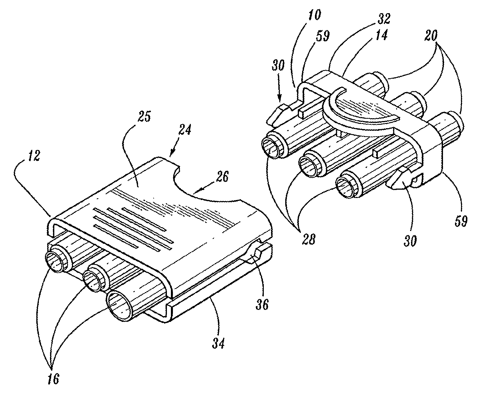
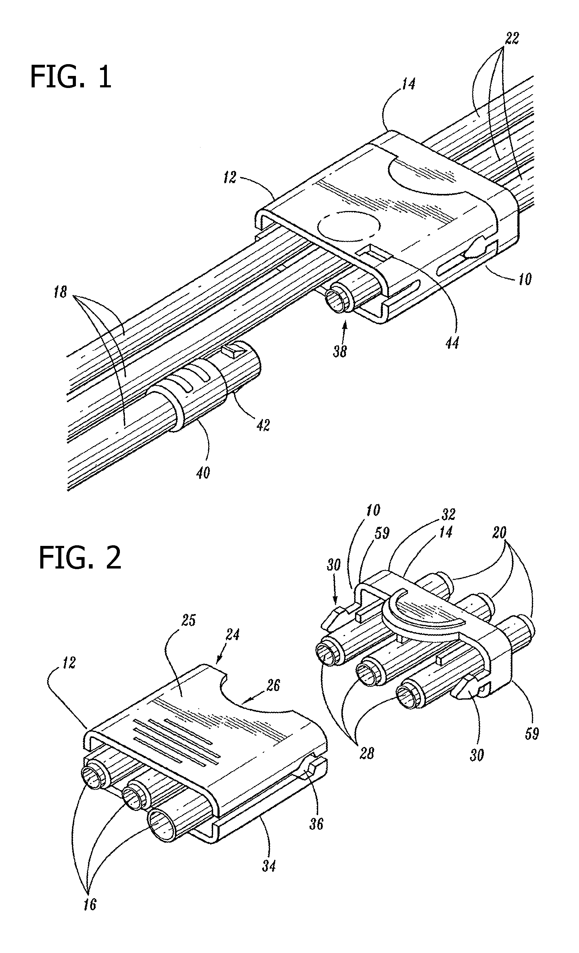
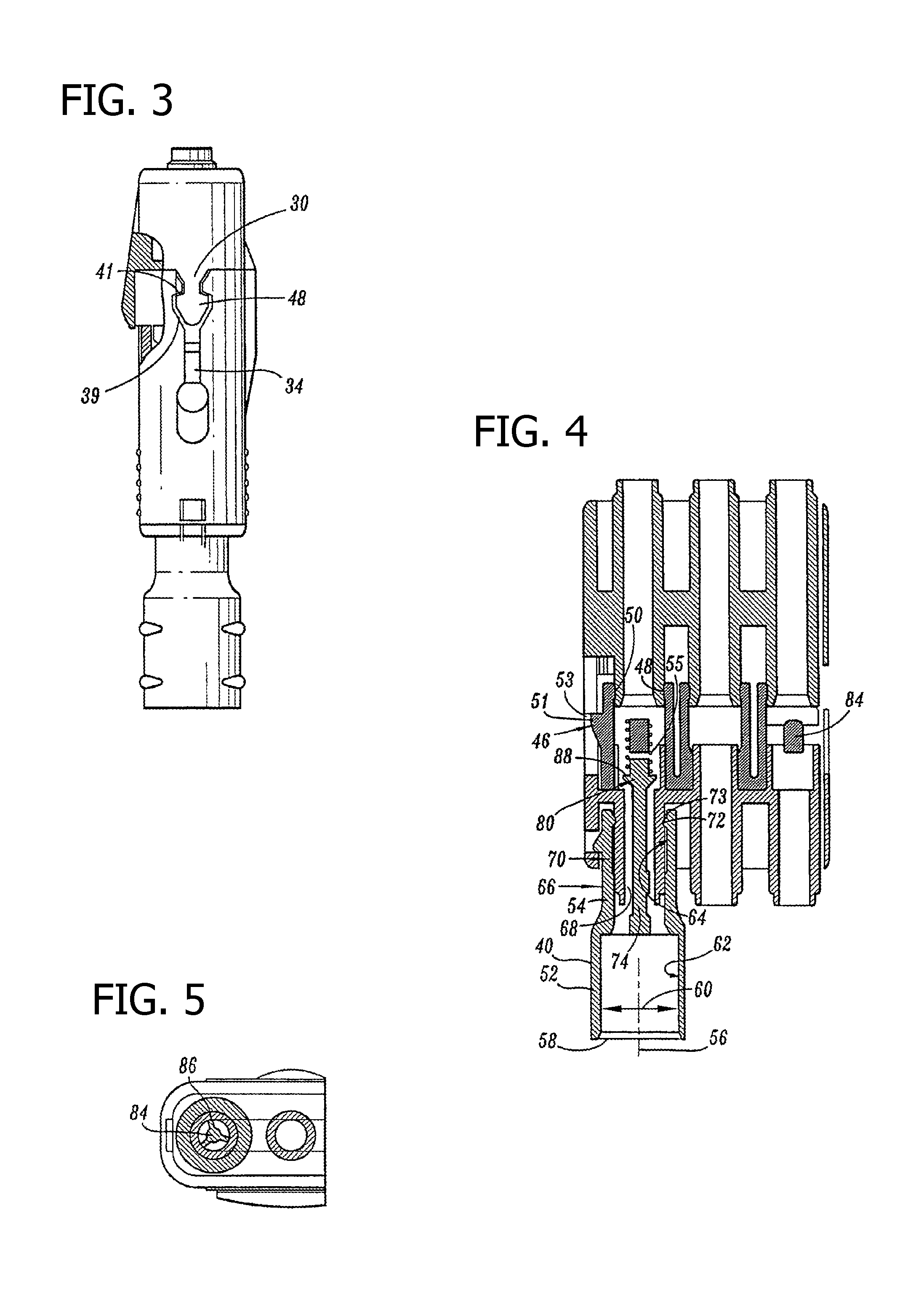
[0059]The exemplary embodiments of the fluid conduit connector apparatus and methods of operation disclosed are discussed in terms of prophylaxis compression apparatus and vascular therapy including a prophylaxis compression apparatus for application to a limb of a body and more particularly in terms of a compression apparatus having removable portions. It is envisioned that the present disclosure, however, finds application with a wide variety of pneumatic systems having removable fluid conduits, such as, for example, medical and industrial applications requiring timed sequences of compressed air in a plurality of air tubes.

[0060]In the discussion that follows, the term “proximal” refers to a portion of a structure that is closer to a torso of a subject and the term “distal” refers to a portion that is further from the torso. As used herein the term “subject” refers to a patient undergoing vascular therapy using the prophylaxis sequential compression apparatus. According to the pre...


PUM


Abstract

A fluid conduit connector apparatus that the approximates pneumatic characteristics of a removed pneumatic system component when a fluid conduit is removed from a pneumatic system. The fluid conduit connector apparatus includes a port portion having a valve disposed therein. The valve closes to provide a reduced fluid orifice when a fluid conduit is removed from the port. The reduced fluid orifice is configured to provides pneumatic characteristics of the device being disconnected to facilitate uninterrupted operation of a timed pressure source having pneumatic sensing capability.

Description

BACKGROUND[0001]1. Technical Field[0002]The present disclosure generally relates to the field of fluid conduit connectors for application to multiple fluid line systems and more particularly to fluid line connectors having a valved port.[0003]2. Description of the Related Art[0004]Medical conditions that form clots in the blood, such as deep vein thrombosis (DVT) and peripheral edema, are a major concern to immobile medical patients. Such patients include those undergoing surgery, anesthesia, extended periods of bed rest, etc. These blood clotting conditions generally occur in the deep veins of the lower extremities and / or pelvis. These veins, such as the iliac, femoral, popiteal and tibial return deoxygenated blood to the heart. When blood circulation in these veins is retarded due to illness, injury or inactivity, there is a tendency for blood to accumulate or pool. A static pool of blood provides an ideal environment for dangerous clot formations. A major risk associated with thi...

Claims


Application Information

Patent Timeline
Patent Type & Authority Patents(United States)
IPC IPC(8): F16L37/23A61F5/00F16K51/00F16L39/00F16L37/56
CPCA61M39/105F16L37/56A61M2039/1077A61M2039/1088Y10T137/87965Y10T137/0447
Inventor TESLUK, CHRISTOPHERBOCK, MALCOLM
Owner KPR U S LLC
Learn More