
Flat panel antenna

a flat panel antenna and antenna technology, applied in the direction of antennas, radiating element structural forms, electrical devices, etc., can solve the problems of loss and impedance, failure to meet the strict requirements of antennas with exact specifications, and poor radiation efficiency of the prior art flat panel antennas, so as to improve radiation efficiency, widen work bandwidth, and reduce the effect of return loss

Inactive Publication Date: 2009-02-10
JOYMAX ELECTRONICS CO LTD
View PDF3 Cites 0 Cited by
  • Summary
  • Abstract
  • Description
  • Claims
  • Application Information

AI Technical Summary

Benefits of technology

"The present invention is a flat panel antenna that allows for precise control of its impedance. This results in a more efficient antenna that can work over a wider range of frequencies and has reduced signal loss. The antenna includes a horizontal ground plane, a vertical ground plane, and a radiation metal member. An extension member extends from the vertical ground plane and penetrates into the radiation metal member for precise control of the antenna's impedance. Overall, this design improves the performance of the antenna and allows for better control of its impedance."

Problems solved by technology

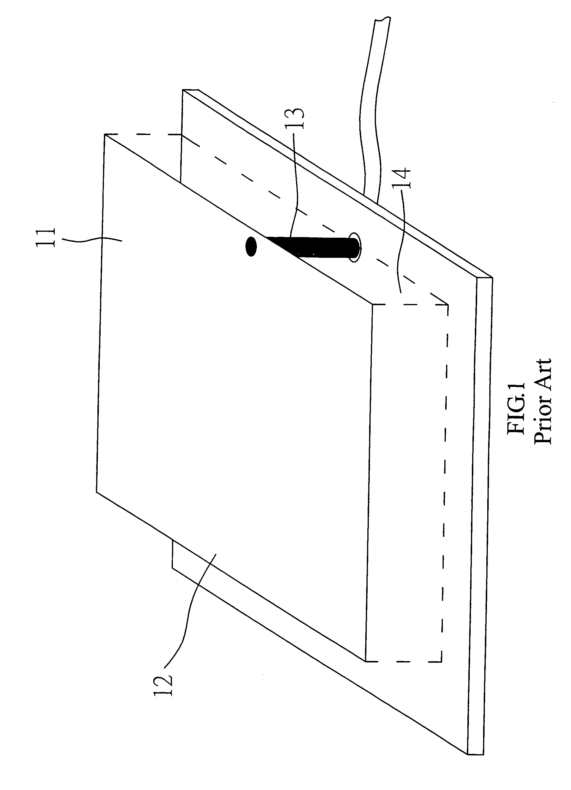
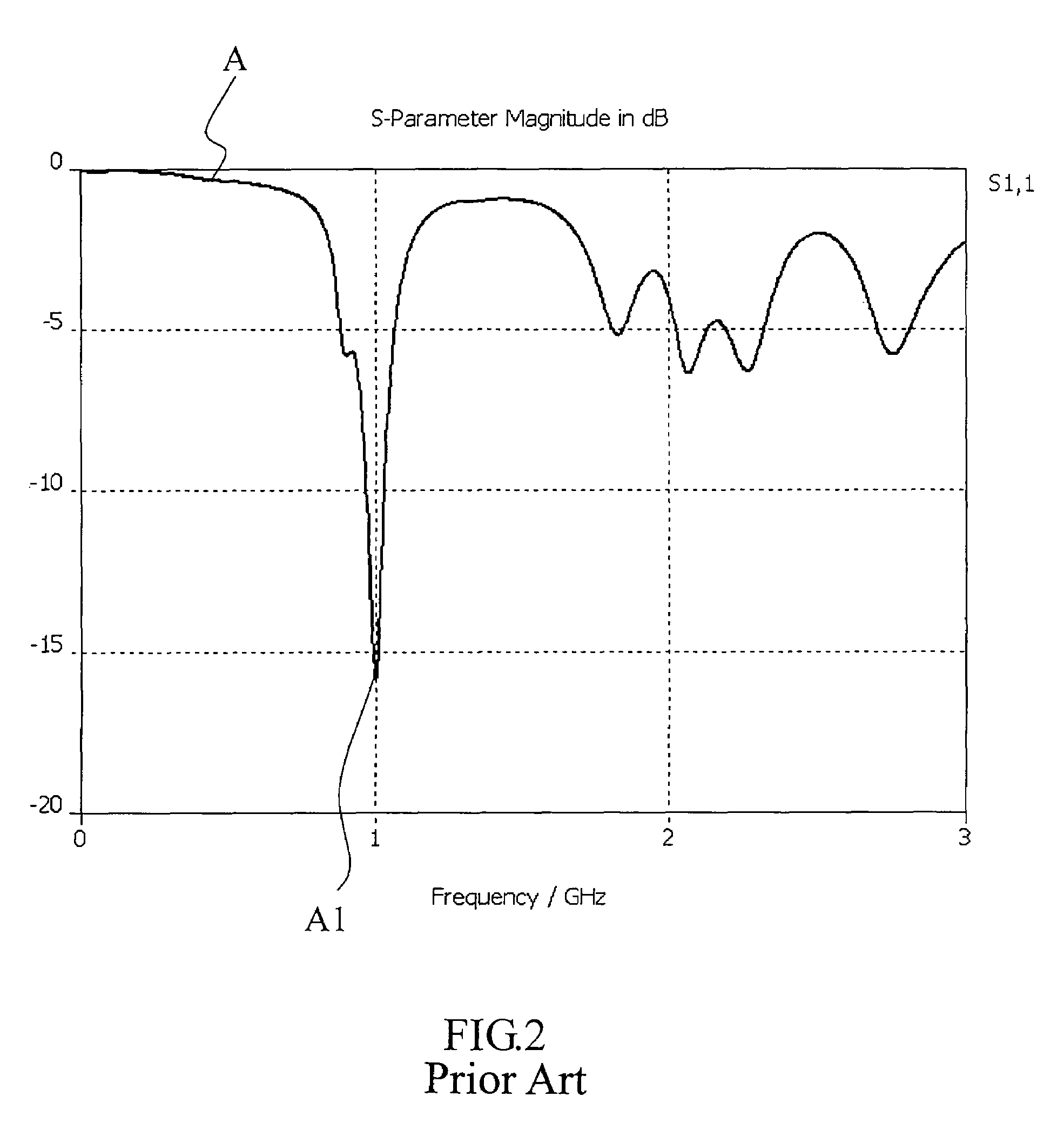
Both of return loss and impedance of the flat panel antenna of the prior art though meet the criteria generally acceptable in the trade, fail to comply with strict requirements of an antenna with exact specifications, e.g., the one for the substrate station or Radio Frequency Identification(RFID) READER.
Furthermore, the radiation efficiency of the flat panel antenna of the prior art is also comparatively poor due to its greater impedance.

Method used


Image

  • Flat panel antenna
  • Flat panel antenna
  • Flat panel antenna

Examples


Embodiment Construction

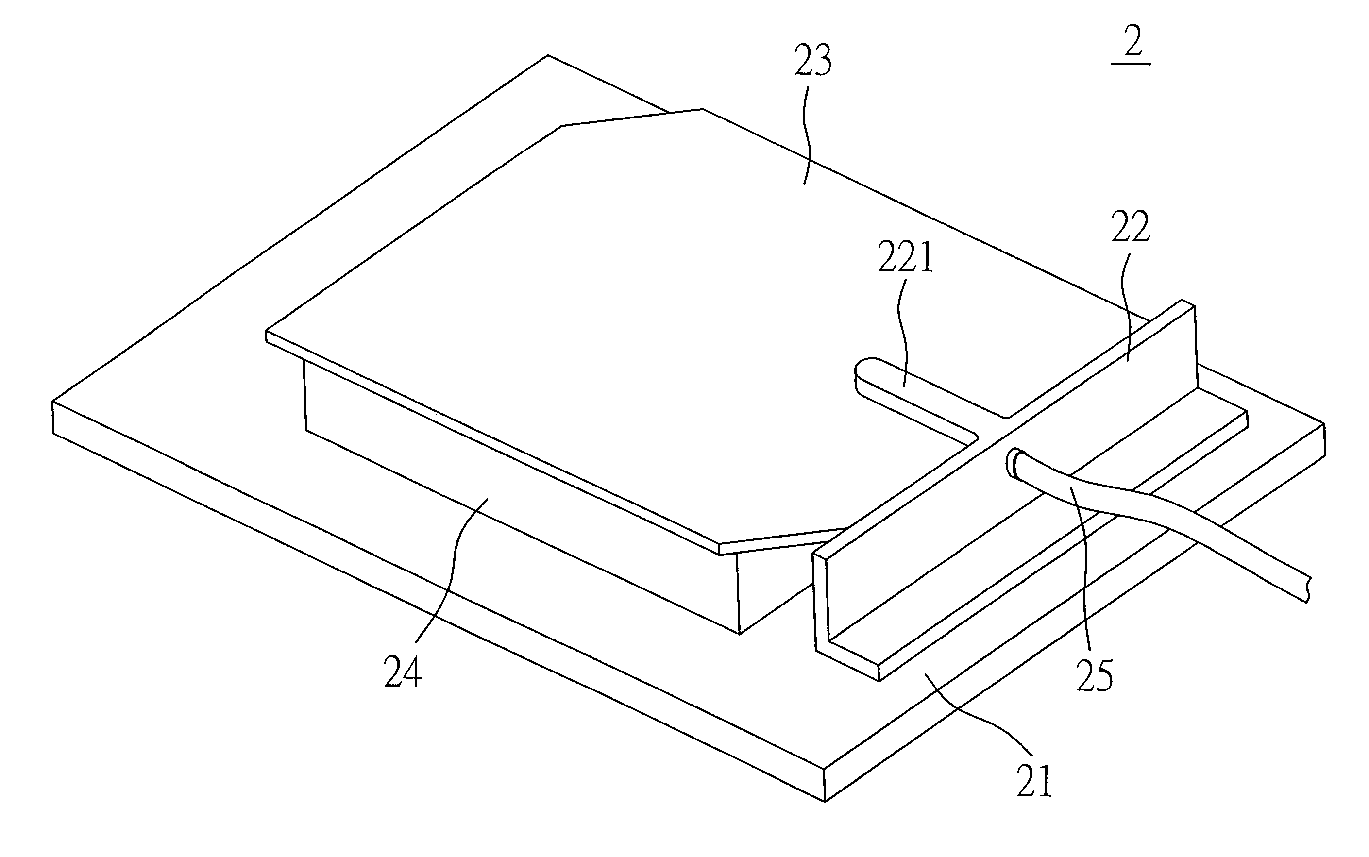
[0018]Referring to FIGS. 4 and 5 for a preferred embodiment of the present invention, a flat panel antenna 2 includes a vertical ground plane 22 and a horizontal ground plane 21 disposed at a right angle to each other with both planes 21, 22 made of metal or other conductive device; a radiation metal member 23 in square provided with a pair of diagonal cutting angles is disposed above and in parallel with the horizontal ground plane 21; a substrate 24 relates to air with a dielectric constant approaching 1 or to a medium with its dielectric constant close to the air is disposed between the horizontal ground plane 21 and the radiation metal member 23; and a feeding device 25 for signal transmission penetrates through the vertical ground plane 22 to connect to the radiation metal member 23.

[0019]The vertical ground plane 22 is disposed at a level higher than that of the radiation metal member 23. An extension member 221 extends from the vertical ground plane 22 facing the direction of...


PUM


Abstract

A flat panel antenna includes a horizontal ground plan, a vertical ground plane, a radiation metal member disposed over and in parallel with the horizontal ground plane; the vertical ground plane being disposed at a level higher than that of the radiation metal member, an extension member extending from the vertical ground plane in the direction of and in parallel with the radiation metal member to penetrate into the radiation metal member for a proper length for precise control impedance of the antenna for the normalized impedance to approach 1, i.e. 50-ohm of the system impedance of the antenna to upgrade radiation efficiency of the flat panel antenna.

Description

BACKGROUND OF THE INVENTION[0001](a) Field of the Invention[0002]The present invention is related to a flat panel antenna, and more particularly, to one that is capable of precise control of the impedance of the flat panel antenna with a value of normalized impedance approaching 1, i.e., the antenna impedance approaches 50Ω of the system impedance to upgrade radiation efficiency of the flat panel antenna.[0003](b) Description of the Prior Art[0004]Advanced communication technology has expands its applications in technology products; and communication products also tends to be more diversified making the design and study of antenna even critical in determination of the transmission and receiving quality. The antenna relates to a device to either radiate or receive electron magnetic (EM) waves and generally the features of an antenna can be made clear by its work frequency, radiation pattern, return loss and antenna gain parameters.[0005]A flat panel antenna of the prior art as illust...

Claims


Application Information

Patent Timeline
Patent Type & Authority Patents(United States)
IPC IPC(8): H01Q1/38
CPCH01Q9/0407H01Q9/0428H01Q9/045
Inventor WAN, TZE-CHUNG
Owner JOYMAX ELECTRONICS CO LTD
Learn More