
Method and device for packaging

a packaging and method technology, applied in the field of packaging methods and devices, can solve the problems of high personnel costs, excessive film remains and creases, and deterioration of storage life, and achieve the effect of pleasing appearan

Active Publication Date: 2009-02-10
MULTIVAC SEPP HAGGENMULLER GMBH & CO KG
View PDF32 Cites 24 Cited by
  • Summary
  • Abstract
  • Description
  • Claims
  • Application Information

AI Technical Summary

Benefits of technology

[0005]It is an object of the invention to provide a method and a device as well as a package enabling a long storage life of food such as meat, wherein, for marketing, the package shall have an appealing appearance.

Problems solved by technology

The problem occurring with some prior methods and devices is that liquid may leak out during the time of storage and ripening, deteriorating the storage life by an enhanced growth of germs in the liquid.
Since the bags are always bigger than the products, excessive film remains and creases can develop.
A disadvantage of this method of packaging is the high personnel costs.
It has the disadvantage that the lower film and the upper film are in contact with each other without being sealed together in a region between the product and the sealing rim, and that creases exist in the region in which the lower film and the upper film are in contact.

Method used


Image

  • Method and device for packaging
  • Method and device for packaging
  • Method and device for packaging

Examples


first embodiment

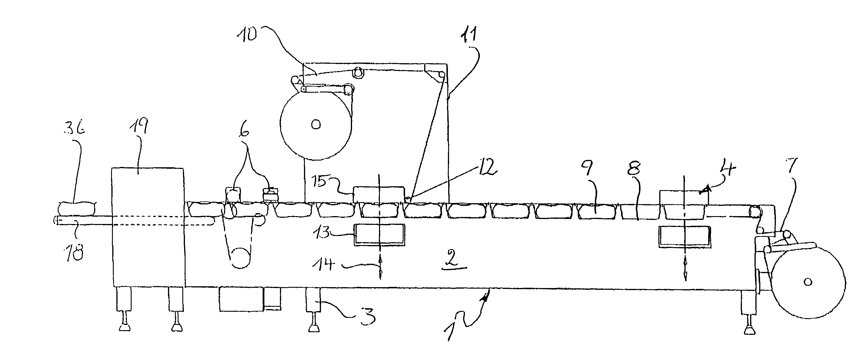
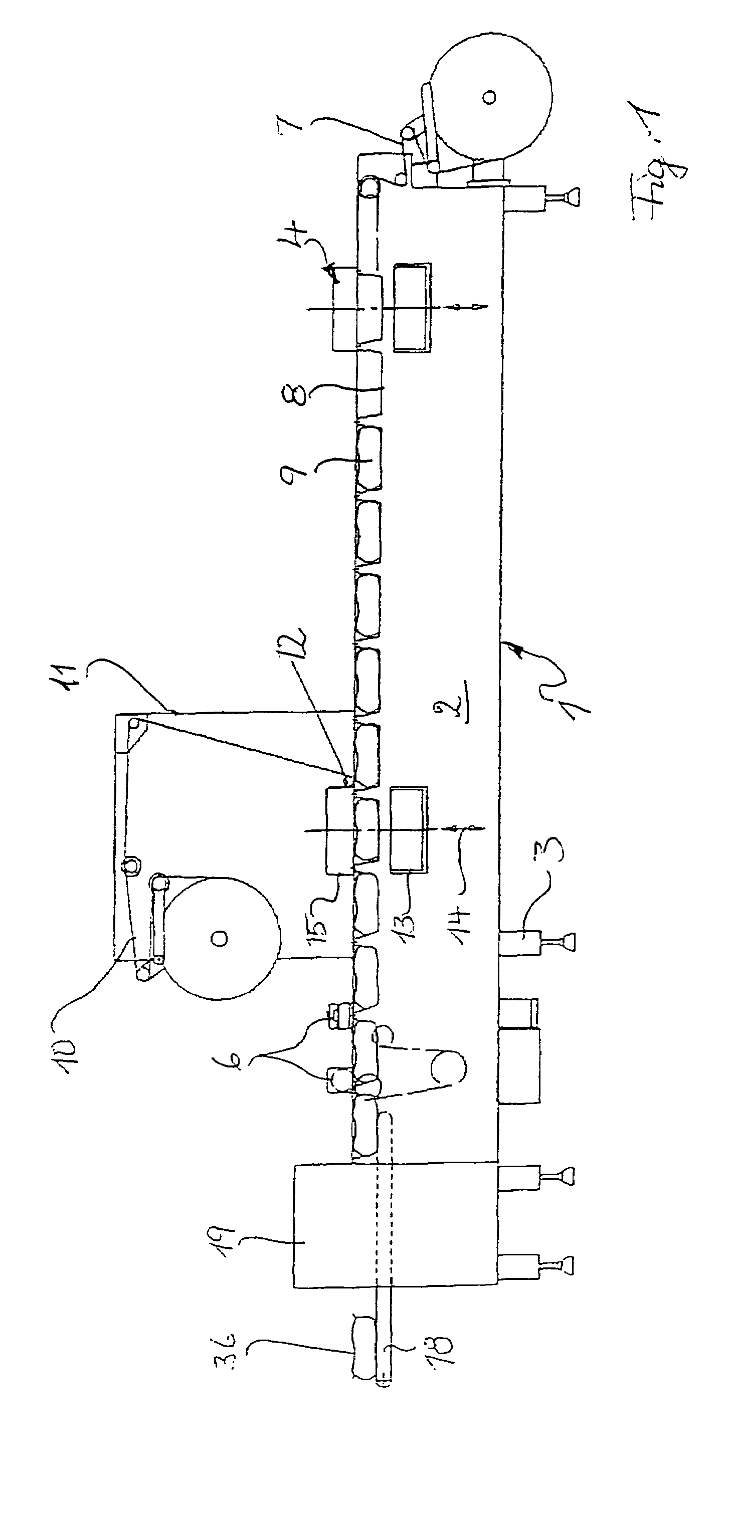
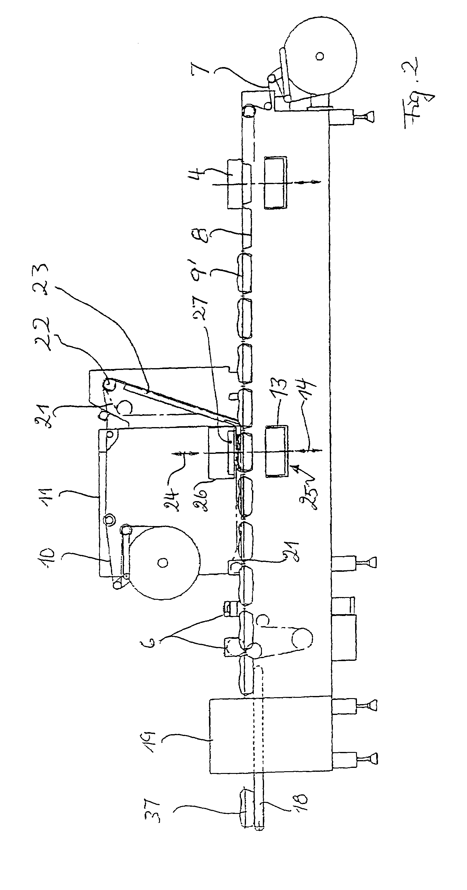
[0028]When operated, for supply, the two parts 13 and 26 are held in the position shown in FIG. 2 separated from each other so that the filled package with the upper and the lower film is insertable. Then, the two parts are brought together such that the contact area is in the plane of the lower film and that the edges of the lower film and the upper film are held upon each other. In this way, in the evacuating and sealing station a stretching of the upper film enabled by the pre-heating takes place. Here, like in the first embodiment, the shrinking onto the good is performed for the lower film as well as for the upper film. As in the case of the embodiment described first, an additional shrinking is performed in the additional shrinking apparatus 19 and in consequence the formed package 37 adopts the appearance as shown in FIG. 8, i.e. the package section 17 initially existent between the product region and rim 16 vanishes.

[0029]The embodiment shown in FIG. 3 is formed to accommoda...

second embodiment

[0030]An additional forming station 28 is provided in the section between the pulley 22 and the input side of the evacuating and sealing station 35, thus in the region in which the heating apparatus 23 is provided in the On the side of the upper film plane facing the good to be packaged it has a stationary part 30 corresponding to the upper part of the forming station 4 and, on the opposite side of the film plane 1, it has an upper part 32 reciprocating in the direction of the arrow 31. The upper part corresponds to the lower part of the forming station 4. The forming station 28 functions in the same way as the forming station 4 and generates a container part 33 projecting upward above the projecting product by deep-drawing.

[0031]The evacuating and sealing station 35 differs from the station described in FIG. 2 in that the cavity 33′ has a size appropriate for accommodating the container part 33.

[0032]In operation, the good 9″ to be packed is inserted into the containers in the low...


PUM

PropertyMeasurementUnit
timeaaaaaaaaaa
shrinking forcesaaaaaaaaaa
temperatureaaaaaaaaaa

Abstract

A method for packaging a good by means of a package formed of a shrinkable lower film 7 and an upper film 10 is provided. The lower film may be deep-drawn to form a container for accommodating the good, and after filling in the good, an upper film may be supplied for covering. The such-formed package is sealed and then may be subjected to shrinking in an evacuating and sealing station. Consecutively to the evacuating and sealing, an additional shrinking may be performed by subjecting the package to heat from all sides, so as to remove the film section having developed between the part of the lower and the upper film directly resting against the good and the sealing rim 16. A corresponding device for executing the method is indicated.

Description

FIELD OF THE INVENTION[0001]The invention relates to a method for packaging a good in a shrink package as well as to a device for executing the method and to a package made of shrinkable film.BACKGROUND AND SUMMARY OF THE INVENTION[0002]The method and the device disclosed herein serve to package perishable food such as meat products. The problem occurring with some prior methods and devices is that liquid may leak out during the time of storage and ripening, deteriorating the storage life by an enhanced growth of germs in the liquid.[0003]In practice, in a simple case, meat pieces are placed in an appropriate film bag and evacuated and sealed in a vacuum chamber machine. Since the bags are always bigger than the products, excessive film remains and creases can develop. When using a shrinkable film, the wrapping is shrunk by a subsequent heat wrapping on the package and a skin-tight fitting of the film is attained. A disadvantage of this method of packaging is the high personnel cost...

Claims


Application Information

Patent Timeline
Patent Type & Authority Patents(United States)
IPC IPC(8): B65B31/00B65B25/06B65B47/02B65B53/04B65B9/04B65B31/02B65B53/02
CPCB65B9/04B65B31/021B65B53/02B65B25/065
Inventor NATTERER, HANSSPARAKOWSKI, HELMUT
Owner MULTIVAC SEPP HAGGENMULLER GMBH & CO KG
Learn More