
Single cycle and equilibrium fuel loading method and system to reduce cycle outage in a boiling water nuclear reactor

a fuel loading method and single cycle technology, applied in the direction of nuclear elements, instruments, greenhouse gas reduction, etc., can solve the problems of increasing the risk of placing a bundle at an incorrect core position, complex core loading plans and maps, and requiring many days to move all or just most bundles

Active Publication Date: 2009-01-20
GLOBAL NUCLEAR FUEL -- AMERICAS
View PDF3 Cites 5 Cited by
  • Summary
  • Abstract
  • Description
  • Claims
  • Application Information

AI Technical Summary

Benefits of technology

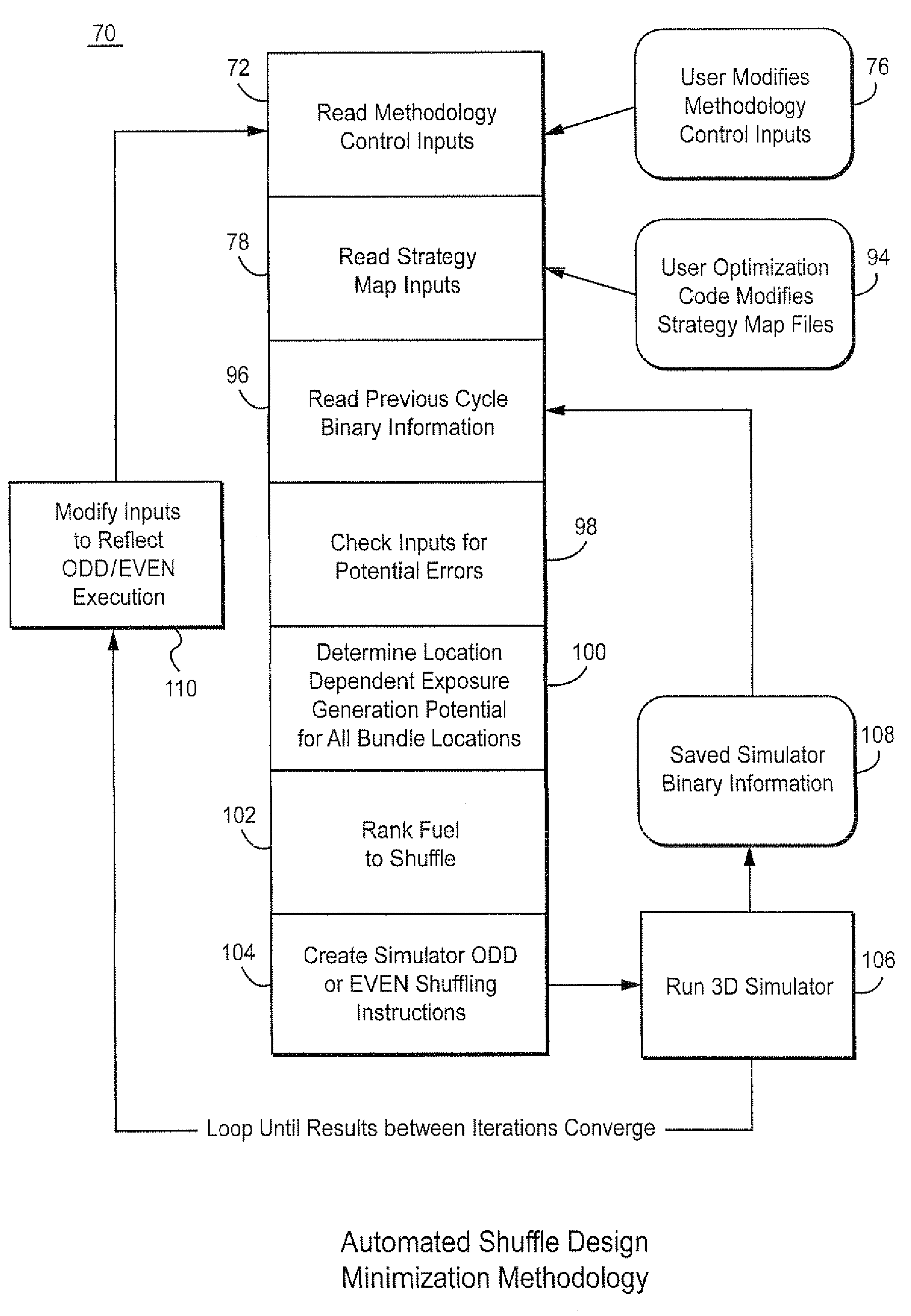
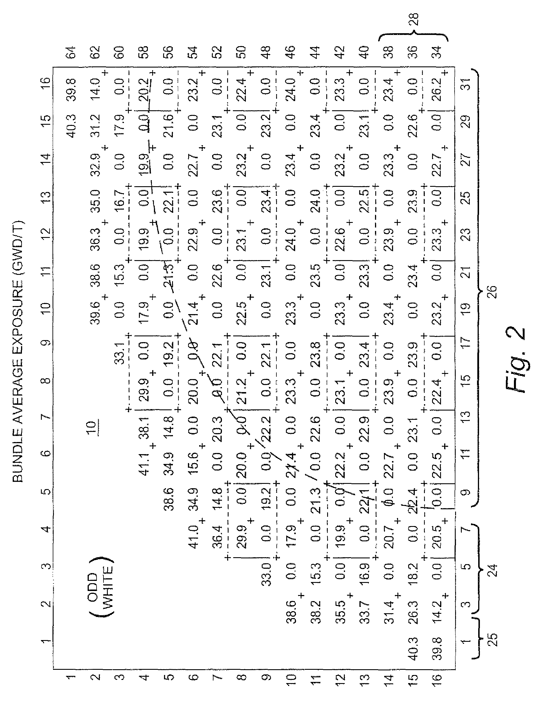
"The patent describes a method for generating fuel loading maps for a nuclear reactor core. These maps identify the locations in the core where fuel bundles will be shifted during refueling cycles. The method includes generating a map for each cycle of refueling, with one map for even cycles and one map for odd cycles. The maps also identify which fuel bundles will be shifted during each cycle. The method also includes comparing the maps from two cycles and reporting an equilibrium fuel loading strategy for the core if the maps converge. The method helps ensure efficient and safe refueling of the nuclear reactor core."

Problems solved by technology

In the past, core loading plans and maps have been complex and involved moving most fuel bundles in a core.
To move all or just most of the bundles can require many days.
Although bundle placement mistakes are rare, the risk of placing a bundle at an incorrect core position increases with the number of bundles to be placed.
Excessive shuffling increases the time needed to refuel a core and increase the risk that bundles will be placed in an incorrect core location.

Method used


Image

  • Single cycle and equilibrium fuel loading method and system to reduce cycle outage in a boiling water nuclear reactor
  • Single cycle and equilibrium fuel loading method and system to reduce cycle outage in a boiling water nuclear reactor
  • Single cycle and equilibrium fuel loading method and system to reduce cycle outage in a boiling water nuclear reactor

Examples


Embodiment Construction

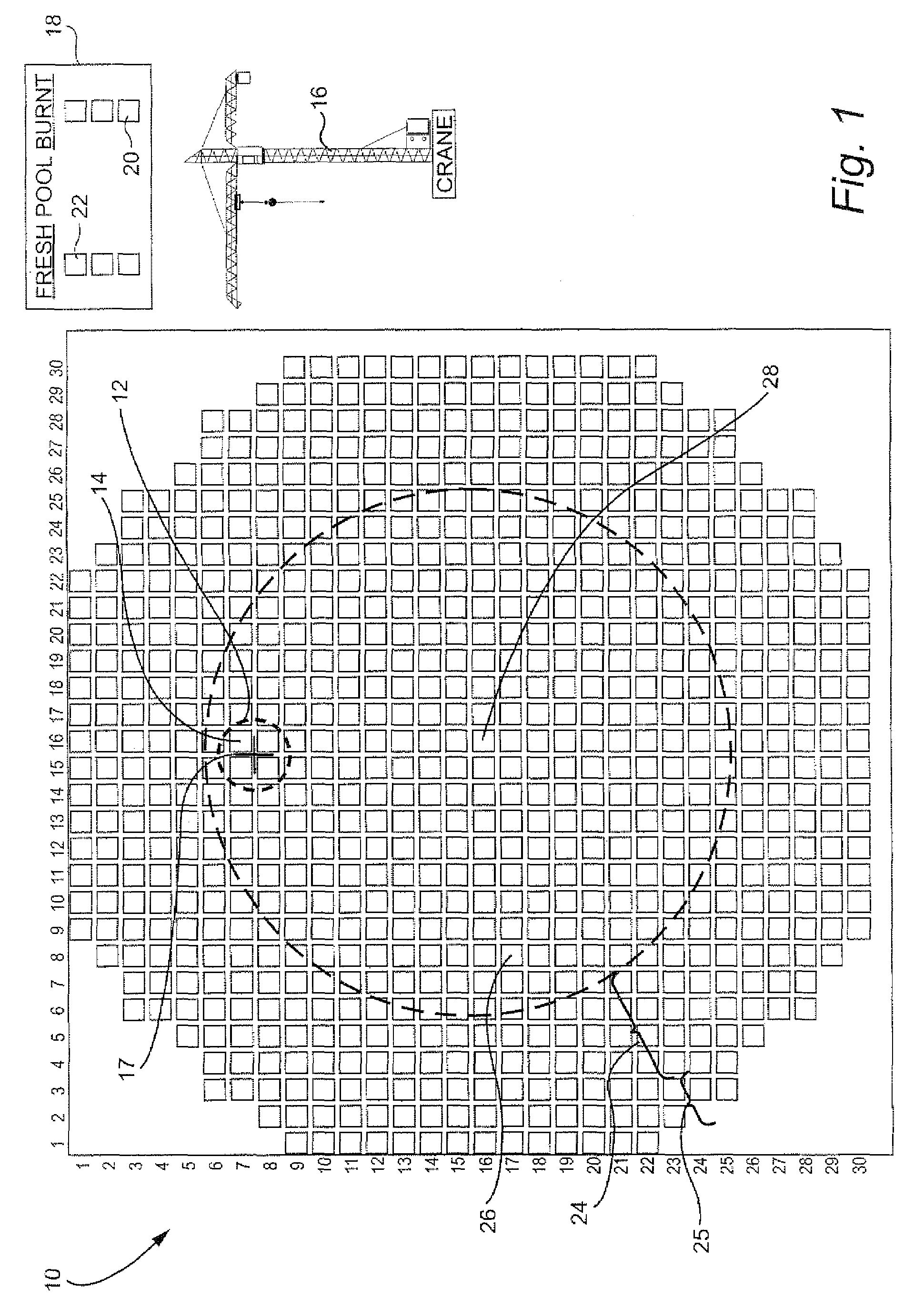
[0028]FIG. 1 is a top down two-dimensional schematic of the core 10 of BWR. The core includes hundreds of control cells 12 (indicated by a dotted line circle). Each control cell includes four fuel bundles 14 arranged around a control blade 17. For simplicity of illustration, only one control blade is shown and only one control cell is designated in FIG. 1. In a typical core, all or most of the fuel bundles are arranged in control cells. The core 10 is arranged in a two-dimensional array in which each fuel bundle is assigned a specific array location.

[0029]The bundle locations in the core are determined by a core loading plan that is executed during core loading while the BWR is off-line and the core is accessible for removing expired fuel bundles, loading fresh fuel bundles and shuffling bundles to be reused in the next cycle. A crane 16 over the core moves each fuel bundle to its proper location in the core. The crane typically moves fuel bundles sequentially, e.g., one at a time. ...


PUM


Abstract

A method for generating fuel loading data for a core in a nuclear reactor, wherein the core includes an array of fuel locations in the core, the method includes: defining an even cycle bundle shift map of fuel bundles to be shifted to another core location during an even fuel loading cycle; defining an odd cycle shift map of fuel bundles to be shifted to another core location during an odd loading cycle, wherein the odd cycle and even cycle are alternative and successive core refueling cycles; defining a discharge map identifying the another locations to receive the bundles from the locations identified in the even and odd cycle shift maps, and generating shuffling instructions indicating which fuel bundles from a prior fuel cycle are to be shifted to one of the another locations of the core for a subsequent fuel cycle, wherein bundles to be shifted during the even fuel loading cycle are selected from the fuel bundles to be shifted identified in the even cycle bundle shift map and bundles to be shifted during the odd fuel loading cycle are selected from the fuel bundles to be shifted identified in the odd cycle bundle shift map.

Description

BACKGROUND OF THE INVENTION[0001]The present invention relates to fuel core loading for refueling a boiling water nuclear reactor (BWR). In particular, the invention relates to core loading strategies for the removal of expired (“burnt”) fuel bundles, installing fresh fuel bundles and shuffling existing fuel bundles to be reused in the core during a subsequent fuel cycle.[0002]The core of a BWR comprises an array of fuel bundles. Each fuel bundle houses an array fuel rods formed of radioactive material. The bundles are arranged in the core based on design constraints such as radioactivity exposure limits for each bundle. The radioactivity of the core heats the water in the reactor. The reactor typically operates on a fuel cycle having a cycle period of, for example, a (1) year, year and a half (1.5) or two (2) years. At the end of each fuel cycle the reactor is shut down to refuel, maintain and repair on the core and reactor vessel. During refueling, fuel bundles are removed from th...

Claims


Application Information

Patent Timeline
Patent Type & Authority Patents(United States)
IPC IPC(8): G06F17/10
CPCG21C3/328G21D3/001Y02E30/31Y02E30/38Y02E30/30Y02E30/00
Inventor RUSSELL, II, WILLIAM EARL
Owner GLOBAL NUCLEAR FUEL -- AMERICAS
Learn More