
Scanning microscope comprising a confocal slit scanner for imaging an object

a scanning microscope and scanner technology, applied in the field of scanning microscopes, can solve the problems of insufficient signal-to-noise ratio of detected image data, too small or even unusable signal-to-noise ratio of detected object points, and overly short dwell period of light beams that illuminate objects, etc., to achieve the effect of improving the signal-to-noise ratio

Active Publication Date: 2009-01-13
LEICA MICROSYSTEMS CMS GMBH
View PDF16 Cites 14 Cited by
  • Summary
  • Abstract
  • Description
  • Claims
  • Application Information

AI Technical Summary

Benefits of technology

[0007]Therefore, it is an object of the present invention to provide a scanning microscope with which an object can be detected with an improved signal-to-noise ratio, even at a high scanning speed.

Problems solved by technology

Particularly in the case of the confocal scanning microscopy of weakly fluorescent specimens, the light beam that serves to illuminate the object has an overly short dwell period per scanned object point.
Consequently, as a rule, the signal-to-noise ratio of the detected object point is too small or, in fact, even unusable.
By nature, fast movements occur here and these can only be meaningfully detected if the detected images of the object can be recorded rapidly enough.
Such a high detection speed normally likewise yields an insufficient signal-to-noise ratio of the detected image data.

Method used


Image

  • Scanning microscope comprising a confocal slit scanner for imaging an object
  • Scanning microscope comprising a confocal slit scanner for imaging an object
  • Scanning microscope comprising a confocal slit scanner for imaging an object

Examples


Embodiment Construction

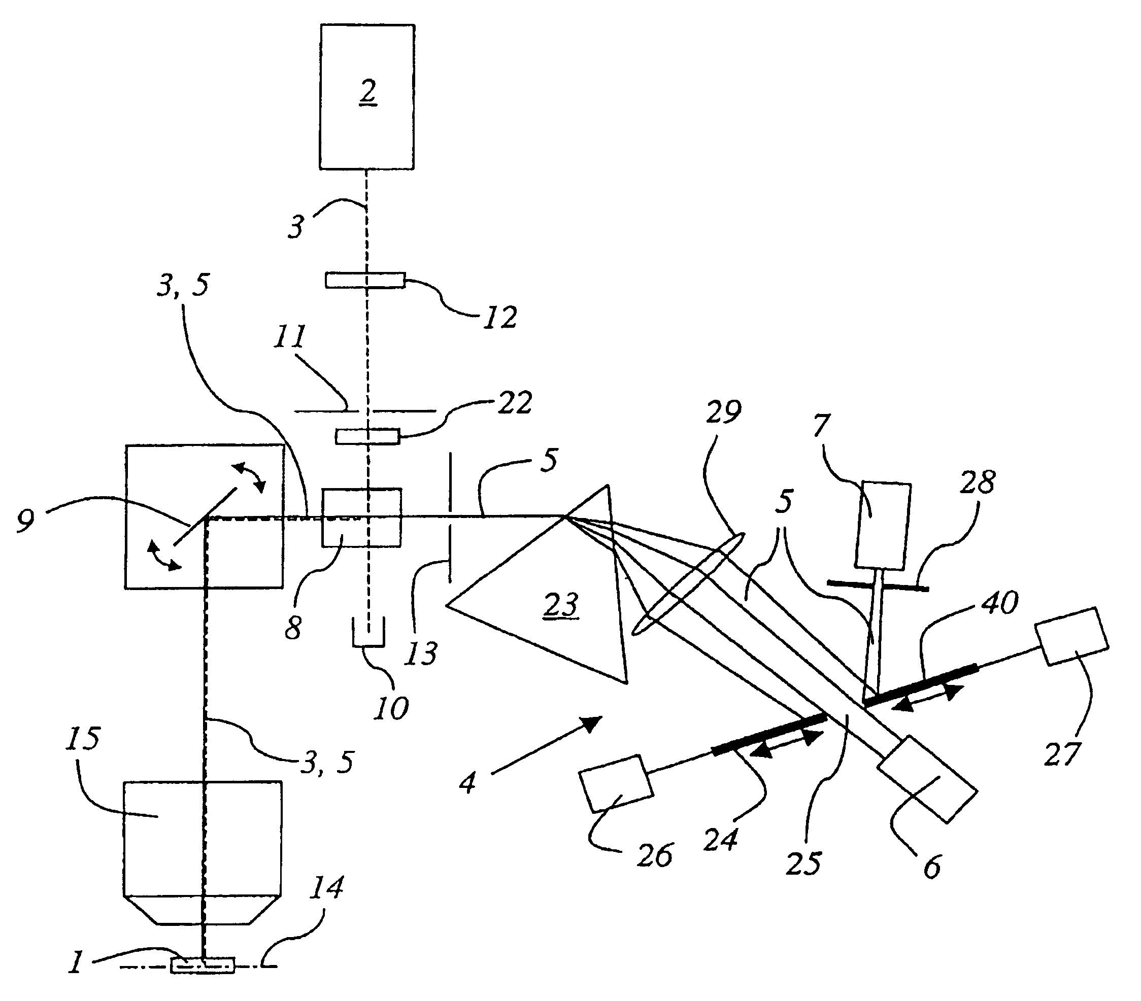
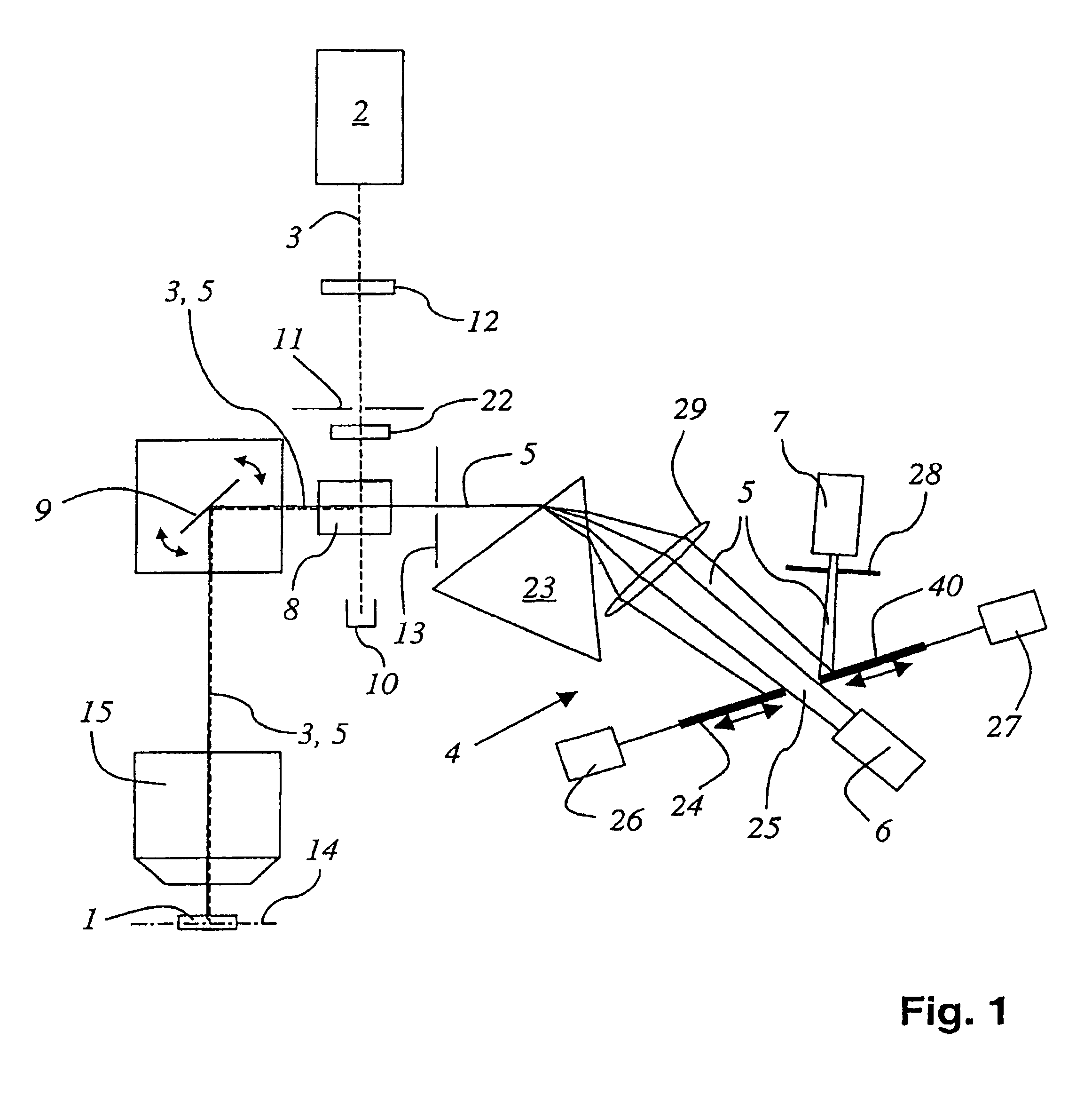
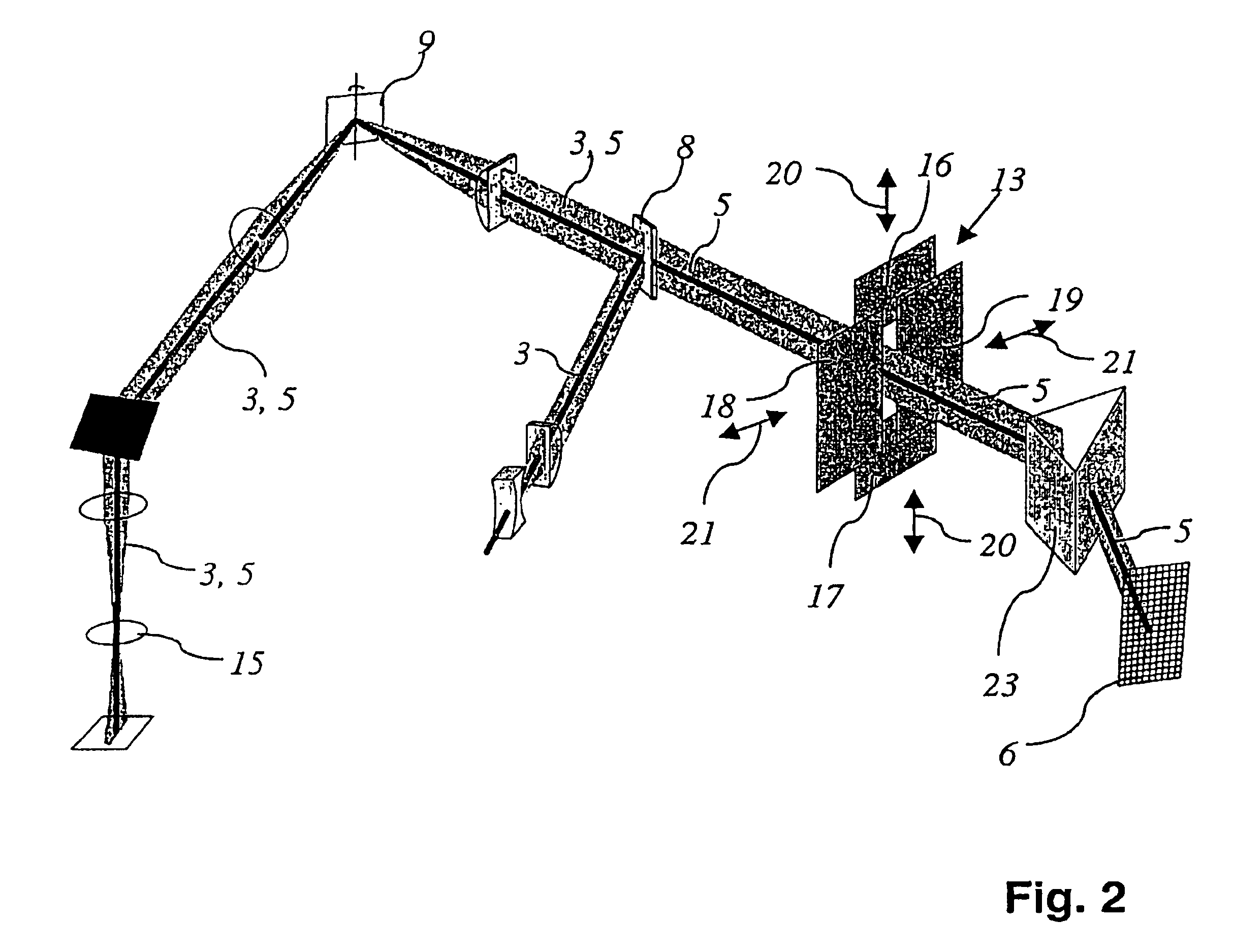
[0043]FIG. 1 shows a scanning microscope for imaging an object 1. The scanning microscope comprises a light source 2 that serves to illuminate the object 1. The illumination beam path 3 extends from the laser light source 2 to the object 1. The scanning microscope also comprises a spectrally selective detection device 4 that can be adjusted in an almost infinitely variable manner and that detects at least one wavelength range of the light extending along the detection beam path 5. The detection beam path 5 extends from the object 1 all the way to the detectors 6 and 7. The spectrally selective element 8 selects light from the laser light source 2 in order to illuminate the object in that it reflects light having a certain wavelength towards the scanning device 9. The unselected light of the laser light source 2—for example, having other wavelengths—passes through the spectrally selective element 8 and is absorbed in the beam trap 10. The light from the laser light source 2 that is r...


PUM


Abstract

A scanning microscope for imaging an object includes a light source and a spectrally selective detection device. An illumination beam path extends from the light source to the object. A detection beam path extends from the object to the detection device. A spectrally selective element useable to select light from the light source is provided. The spectrally selective element is useable to mask out of the detection beam path the selected light from the light source reflected or scattered on the object. An illumination slit diaphragm is disposed in the illumination beam path and configured to generate a linear illumination pattern in a region of the object. A detection slit diaphragm is disposed in the detection beam path and configured to detect the light coming from the linear illumination region from a focal plane so as to provide a confocal slit scanner.

Description

[0001]The present invention relates to a scanning microscope for imaging an object, comprising a light source, a spectrally selective element that can be adjusted in an almost infinitely variable manner, a spectrally selective detection device that can be adjusted in an almost infinitely variable manner, an illumination beam path extending from the light source to the object, a detection beam path extending from the object to the detection device, whereby the spectrally selective element can be used to select light from the light source in order to illuminate the object, whereby the selected light from the light source that is reflected and / or scattered on the object can be masked out of the detection beam path by means of the spectrally selective element, whereby at least one wavelength range of the light extending along the detection beam path can be detected by means of the spectrally selective detection device.BACKGROUND[0002]The term scanning microscope as employed in the prese...

Claims


Application Information

Patent Timeline
IPC IPC(8): G01J3/28G02B21/00
CPCG02B21/0032G02B21/0076G02B21/0084
Inventor KNEBEL, WERNERBIRK, HOLGERSTORZ, RAFAEL
Owner LEICA MICROSYSTEMS CMS GMBH
Learn More