
Mask for sequential lateral solidification and method of performing sequential lateral solidification using the same

a technology of sequential lateral solidification and mask, which is applied in the direction of photomechanical treatment originals, manufacturing tools, instruments, etc., can solve the problems and achieve the effect of increasing process margin and provoking the growth of larger crystal grains

Inactive Publication Date: 2009-01-13
SAMSUNG DISPLAY CO LTD
View PDF22 Cites 4 Cited by
  • Summary
  • Abstract
  • Description
  • Claims
  • Application Information

AI Technical Summary

Benefits of technology

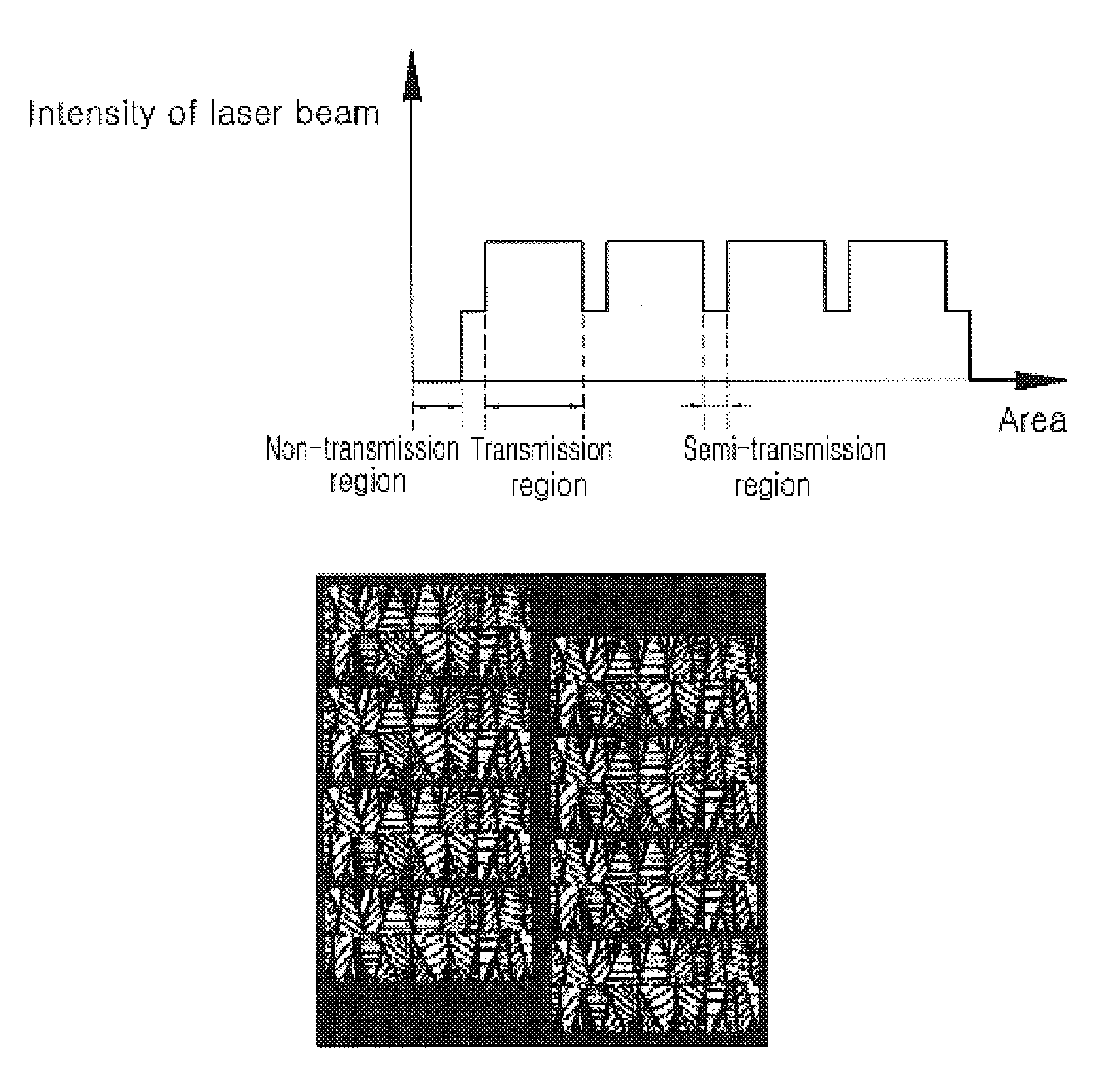
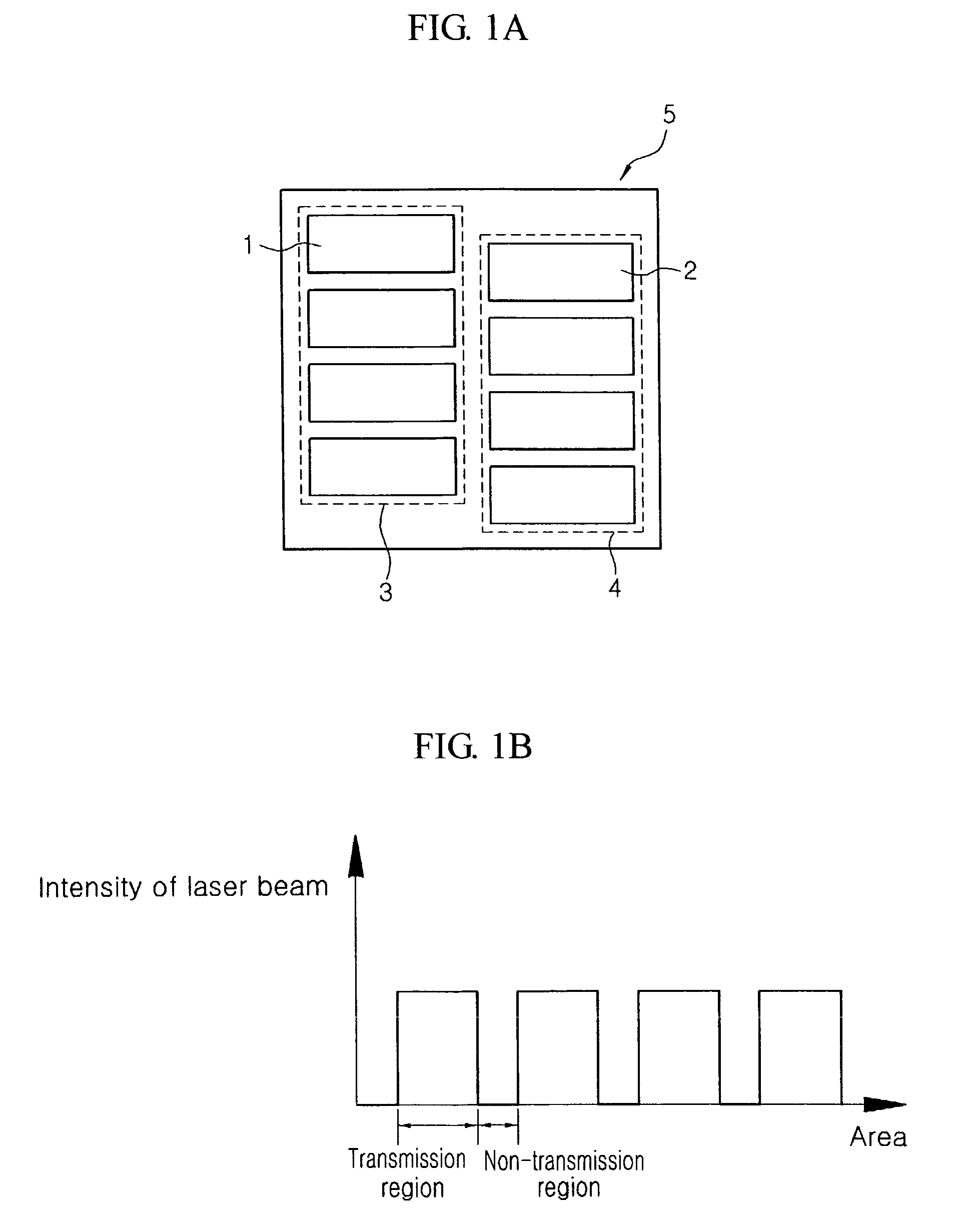
The present invention provides a mask for sequential lateral solidification that improves process margin and induces larger crystal grains. The mask includes a transmission region and a semi-transmission region. The semi-transmission region has a plurality of openings formed into a predetermined shape and disposed at least partially in each area between adjacent slits. The openings are positioned at a predetermined angle with respect to a scanning direction. The mask can improve the overlap between lines and compensate for reduced overlap due to stage vibration. The mask can also include a first slit column and a second slit column separated by a predetermined interval. The first slit column has a plurality of slits that transmit substantially all incident light, while the second slit column has a plurality of slits that transmit a portion less than all incident light. The mask can provide increased process margin, induce larger crystal grains, and improve the quality of the resulting product.

Problems solved by technology

The resultant mask may provide increased process margin, and may induce growth of larger crystal grains.

Method used


Image

  • Mask for sequential lateral solidification and method of performing sequential lateral solidification using the same
  • Mask for sequential lateral solidification and method of performing sequential lateral solidification using the same
  • Mask for sequential lateral solidification and method of performing sequential lateral solidification using the same

Examples


Embodiment Construction

[0050]Hereinafter, preferred embodiments of the present invention will be described in detail with reference to the accompanying drawings.

[0051]FIG. 3 is a schematic diagram illustrating the configuration of a sequential lateral solidification apparatus according to embodiments of the present invention.

[0052]Referring to FIG. 3, the sequential lateral solidification apparatus comprises a laser generator 10, a laser-transforming optic unit 20, a light source-uniforming optic unit 30, a first reflection mirror 40, a second reflection mirror 50, a third reflection mirror 60, a projection lens 70, a stage 80, and a mask 100 including transmission and semi-transmission regions.

[0053]The laser generator 10 generates a pulsed laser with a frequency of about 300 Hz. The laser-transforming optic unit 20 maintains a pulse generated from the laser generator 10 for a certain period of time. The light source-uniforming optic unit 30 maintains the uniformity of laser beam at a constant level. The...


PUM

PropertyMeasurementUnit
frequencyaaaaaaaaaa
widthaaaaaaaaaa
widthaaaaaaaaaa

Abstract

Embodiments of a mask for sequential lateral solidification are disclosed herein. In some embodiments, a mask of the present disclosure comprises a transmission region including a first slit column having a plurality of first slits separated from one another by a predetermined interval, and a second slit column having a plurality of second slits separated from one another by a predetermined interval and disposed adjacent to and offset from the first slit column. An irradiated laser beam is substantially completely transmitted through the transmission region. In some embodiments, the mask includes a semi-transmission region including a first opening pattern disposed at least partially between adjacent first slits and having a plurality of first openings formed into a desired shape, and a second opening pattern disposed at least partially between adjacent second slits and having a plurality of second opening formed into a desired shape. A portion of less than all of the laser beam is transmitted through the semi-transmission region. A method of performing the sequential lateral solidification using the mask is also disclosed herein.

Description

CROSS-REFERENCE TO RELATED APPLICATION[0001]This application claims priority to and the benefit of Korean Patent Application No. 10-2006-0041655, filed in the Korean Intellectual Property Office on May 9, 2006, the entire contents of which are incorporated herein by reference.BACKGROUND OF THE INVENTION[0002]1. Field of the Invention[0003]The present invention relates to a mask for sequential lateral solidification and a method of performing sequential lateral solidification using the same. More specifically, the present invention relates to a mask that may be used for sequential lateral solidification and a method of performing sequential lateral solidification using the same. The method may result in a material in which crystal defects are reduced or eliminated, and which can induce the growth of larger crystal grains.[0004]2. Description of the Related Art[0005]Among crystallization techniques for transforming amorphous silicon into polysilicon, sequential lateral solidification ...

Claims


Application Information

Patent Timeline
Patent Type & Authority Patents(United States)
IPC IPC(8): G03F1/00
CPCB23K26/0656C30B13/24C30B29/06H01L21/02532H01L21/0268H01L21/02686H01L21/02691B23K26/066H01L21/324
Inventor PARK, CHEOL HO
Owner SAMSUNG DISPLAY CO LTD
Learn More