Bulk material handling system and portable loading apparatus thereof

a technology of loading apparatus and loading system, which is applied in the direction of transportation items, loading/unloading vehicle arrangment, and refuse collection, etc., can solve the problem of fixed site location of equipment used for such loading operations, and achieve the effect of enhancing material flow

Inactive Publication Date: 2009-01-13
YOUNG INDS
View PDF14 Cites 8 Cited by
  • Summary
  • Abstract
  • Description
  • Claims
  • Application Information

AI Technical Summary

Problems solved by technology

Typically, equipment used for such loading operations are located at fixed sites not always readily accessible to the containers to be loaded.

Method used


Image

  • Bulk material handling system and portable loading apparatus thereof
  • Bulk material handling system and portable loading apparatus thereof
  • Bulk material handling system and portable loading apparatus thereof

Examples


Embodiment Construction

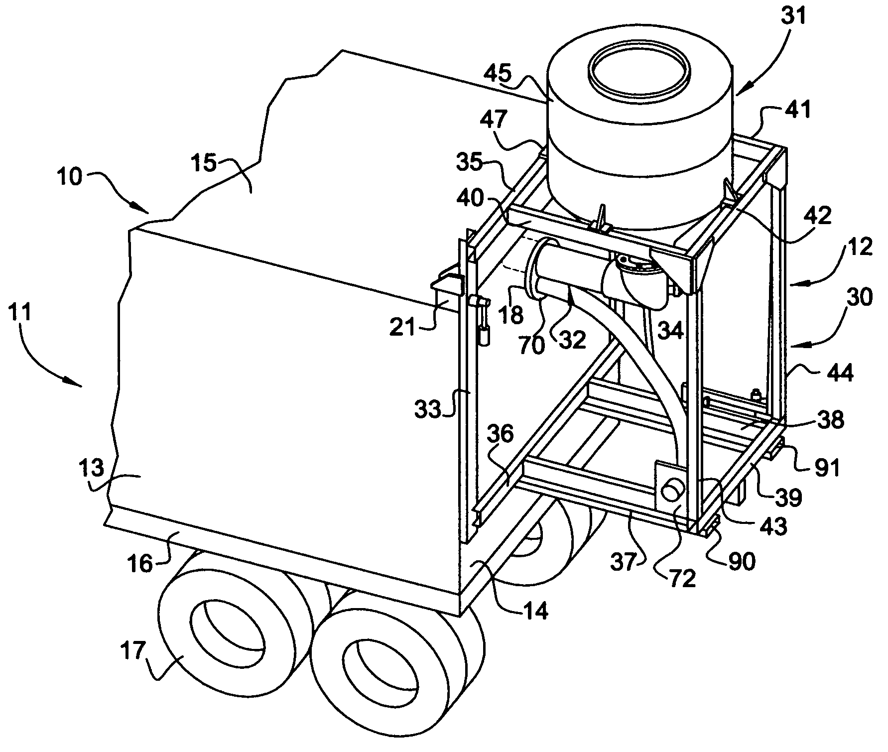
[0011]Referring to FIG. 1 of the drawings, there is illustrated a material handling system 10 which generally includes a container 11 and a bulk material loading apparatus 12. Container 11 is of a rectangular configuration including a bottom wall, a pair of side walls 13, 13, a front wall, a rear wall 14 and a top wall 15. The container is of an intermodal type which may be transported on the bed of a motor vehicle, a railway car or in a ship hold. In the embodiment shown, the container is supported on the flat bed of a vehicle chassis 16 mounted on sets of wheels 17. Disposed within container 11 is a flexible liner formed of a plastic material for holding the bulk material loaded into the container, which is provided with a fill neck. Access to the fill neck of the liner is provided through a closable opening 18 formed in the upper, center portion of rear wall 14 of the container.

[0012]Rigidly secured to the rear corners of upper wall 15 of the container is a pair of mounting block...


PUM


Abstract

A bulk material system generally consisting of a container having an upper wall, a vertical wall and an opening in the vertical wall; a support frame detachably mountable on the upper and vertical walls of the container; a hopper mounted on the support frame; a material conveying conduit mounted on the frame having an inlet communicating with an outlet of the hopper for receiving material therefrom and an end portion with an outlet insertable through the vertical wall opening of the container when the frame is detachably mounted on the container; and a conduit supported on the support frame having an outlet communicating with the material conveying conduit and an inlet communicable with a source of gas under pressure, function to supply gas under pressure to the material conveying conduit for pneumatically conveying material fed from the hopper into the material conveying conduit, therethrough, into the container.

Description

[0001]This invention relates to a bulk material handling system. It further contemplates a portable apparatus for loading such material into a container.BACKGROUND OF THE INVENTION[0002]Bulk materials commonly used in various manufacturing processes typically are transported in intermodal containers mountable on flat beds of motor vehicles, railway cars and ship holds for shipping. Because of the poor flow characteristics of many of such materials, pneumatic conveying methods commonly are employed for loading such materials into containers. The use of such methods, however, requires not only the handling of large volumes of air for conveying the materials but the venting of such air and the removal of airborne particles of such material entrained in the vented air so as not to pollute or contaminate the working environment. Typically, equipment used for such loading operations are located at fixed sites not always readily accessible to the containers to be loaded. Accordingly, it is...

Claims


Application Information

Patent Timeline
Patent Type & Authority Patents(United States)
IPC IPC(8): E02B11/00
CPCB65G67/06B65G69/0491
Inventor BOROCH, ANTHONY
Owner YOUNG INDS
Why Eureka
Try Eureka