
Hospital patient support

a patient support and hospital technology, applied in the field of hospital patient support, can solve the problems of inconvenient and disruptive, inconvenient and disruptive, and the monitoring and potentially diagnosis of problems with patient support can be both time-consuming and costly, and manual systems suffer from the need for considerable physical effort to adjust the height of the patient suppor

Active Publication Date: 2009-01-06
STRYKER CORP
View PDF22 Cites 96 Cited by
  • Summary
  • Abstract
  • Description
  • Claims
  • Application Information

AI Technical Summary

Benefits of technology

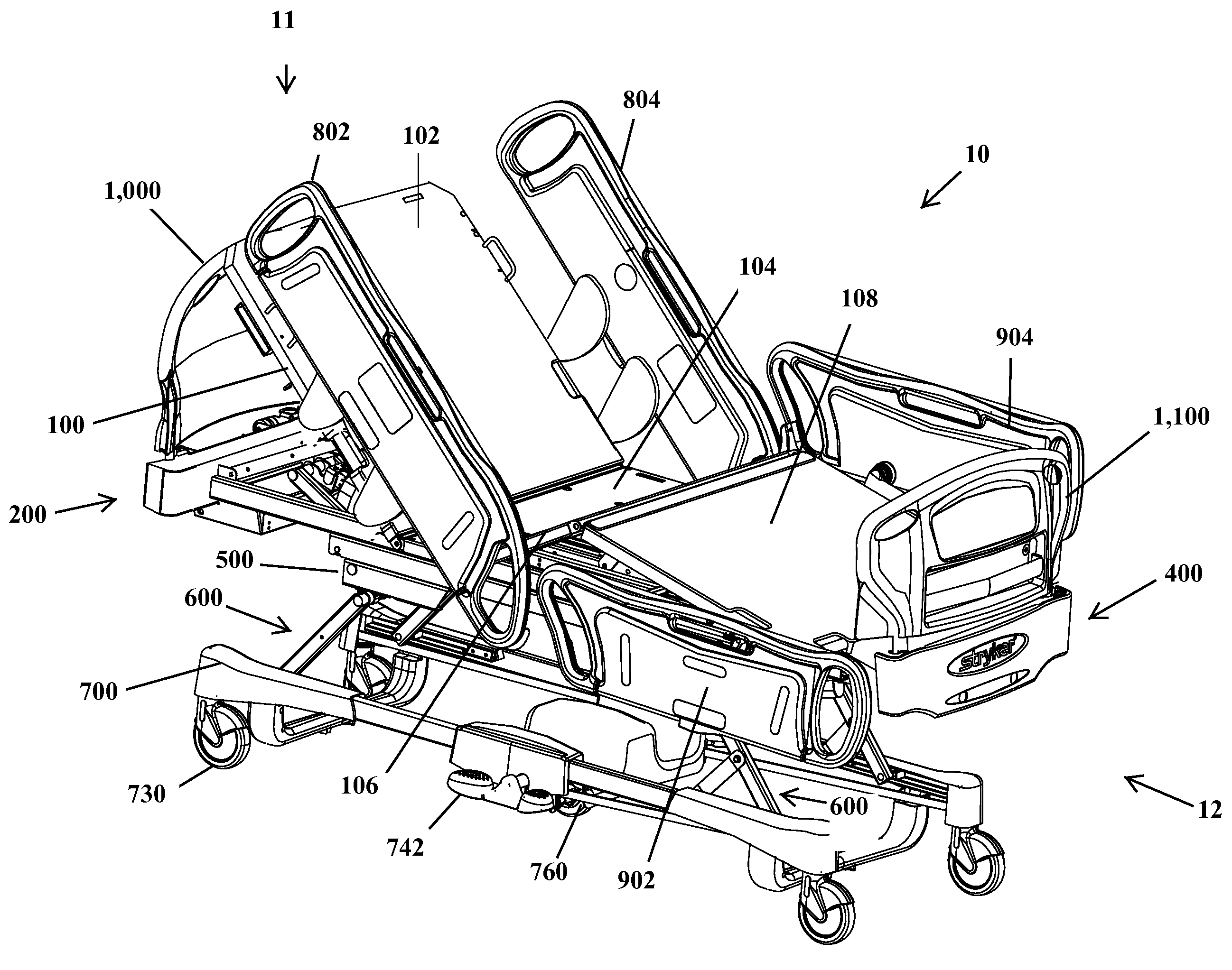
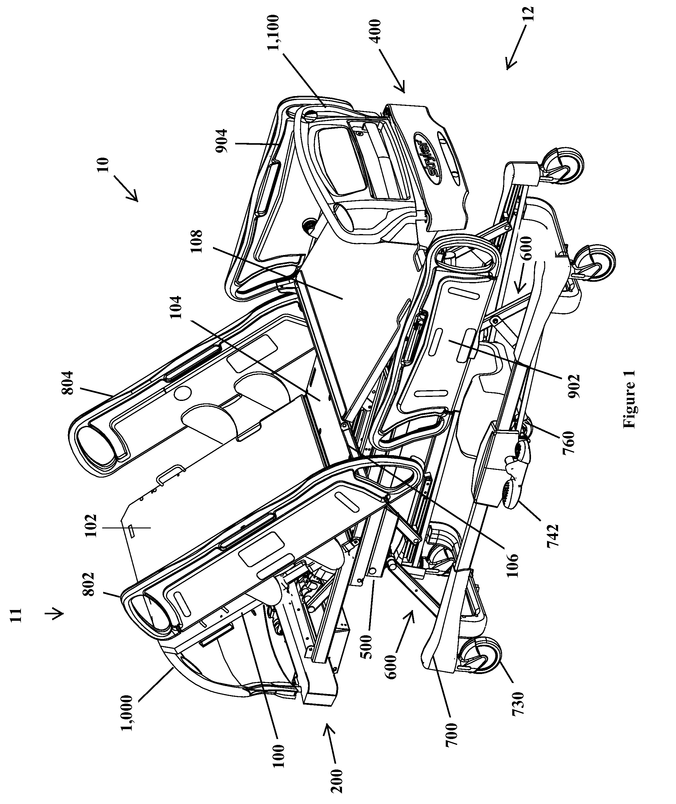
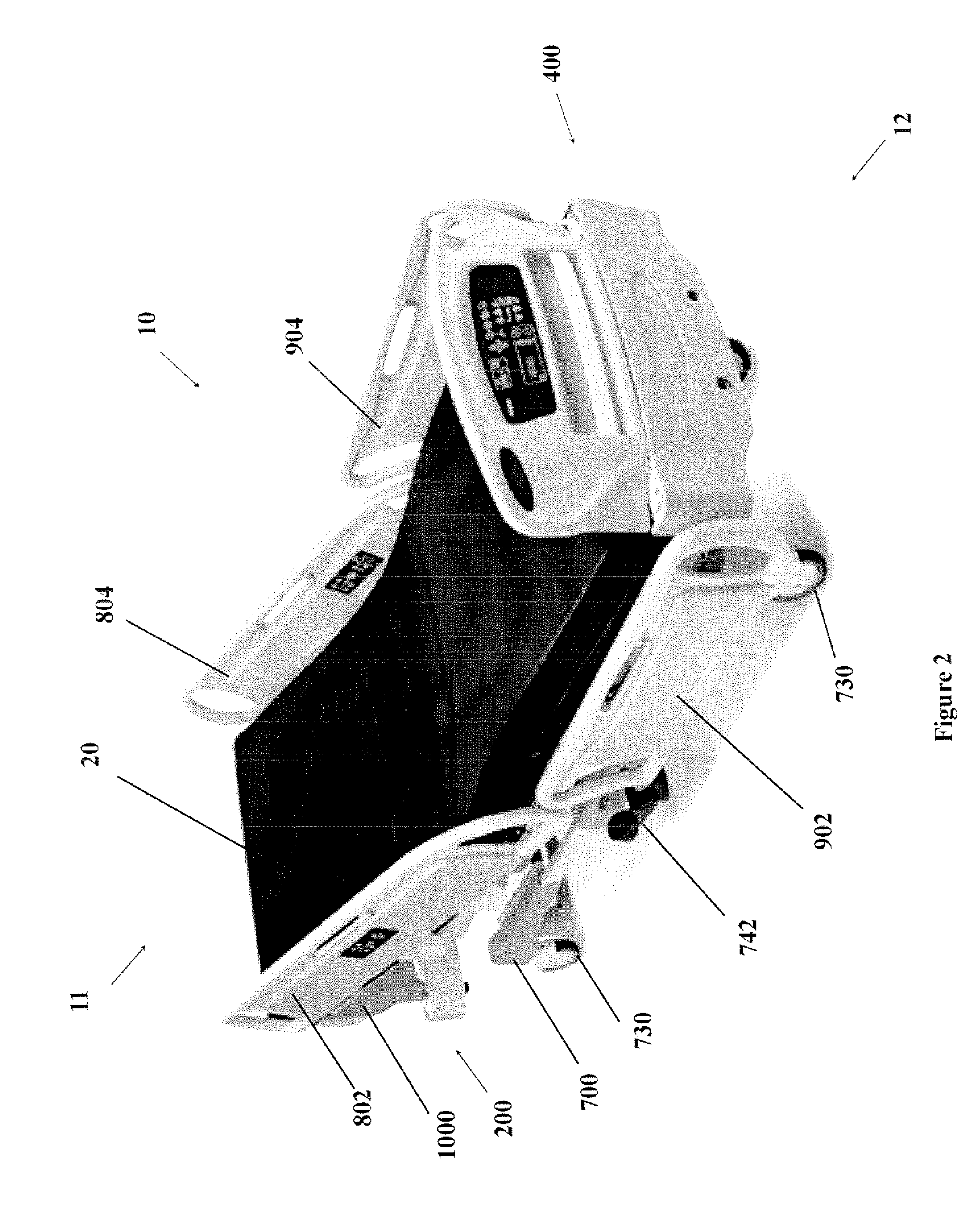
The present disclosure is about a patient support with a head end and a foot end. It includes a lying surface supported by a frame system, head and foot end siderails, a headboard, a footboard, a power system, and a communication system. The frame system allows for pivoting and elevating the patient support. The communication system controls various functions of the patient support and receives data from load cells and tilt sensors to determine patient characteristics. The control system also includes a diagnostic subsystem for detecting and analyzing operational faults of the electronically controlled devices. The technical effects of this patent include improved patient support with advanced features and efficient and reliable operation.

Problems solved by technology

The placement of such equipment can obscure a reading area or control panel located on the footboard.
Furthermore, such equipment may fall off the headboard or other device, thereby resulting in damage.
In order to obtain an accurate weight measurement, patients who are in an articulated patient support often have to be repositioned to the horizontal, which is inconvenient and disruptive.
This form of monitoring and potentially diagnosis of problems with a patient support can be both time consuming and costly.
Such manual systems suffer from the need for considerable physical effort to adjust the patient support height.
Such hydraulic systems are known to be relatively expensive and prone to leakage.
Additionally, prior mechanical systems suffer from excessive complexity, excessive size, a lack of load capacity, and manufacturing difficulties.
Hospital patient support siderails of the prior art comprise support arms, which form undesirable pinch points for users.
The movement of such siderails from the deployed to the stowed positions is often hampered by siderail oscillations.
The siderail falls due to gravity and the movement can jar the patient support and disturb patients.
This is problematic in circumstances where the life of the battery itself has run out or in settings where a suitable power supply to recharge the battery is not available.
Since footboards were not designed to support the hanging of pumps (or other hospital equipment), this current footboards, generates patient support motions and causes damage to pumps (and other equipment) that fall from its hangers.
Ordinarily, there is a tendency for detached headboards or footboards placed in an upright position against an object or structure to slip, thereby causing the headboard or footboard to fall and potentially suffer damage.
In a busy hospital, a discarded headboard or footboard that has fallen to the floor creates a tripping hazard to both staff, who may be carrying equipment or medication and thus have an obstructed view of the floor, and patients, who may have compromised mobility owing to illness.
Preventing slippage, therefore, reduces the likelihood of personal injury stemming from hastily removed headboards and footboards.

Method used


Image

  • Hospital patient support
  • Hospital patient support
  • Hospital patient support

Examples


examples

[0303]Some examples of how the communication system is used to interface with the patient support are provided.

Main Power Switch

[0304]The patient support is equipped with a main power switch located at the head end of the patient support. This power switch must be switched on in order to activate the patient support functions. Should this switch be turned off, or there is other interruption to the power, such as a power failure, the settings of the lockout controls and the calibration data of the Scale and the Patient Support Exit systems are preserved.

Brake / Steer Foot Pedal Control

[0305]The patient support is equipped with two lateral pedals secured to the middle section of the base frame member. The pedals control the brakes and the centrally-located drive wheel 760. The functions of the pedals are determined by the user pushing in a forward or backward motion; such forward or backward motion corresponding to either brake control or steering control as denoted by affixed labels. N...


PUM


Abstract

The patient support with a head end and a foot end comprises a lying surface supported by a frame system. It also comprises a pair of head end siderails, a pair of foot end siderails, a headboard, a footboard, a power system and a communication system. The frame system comprises a lying surface support moveably connected to a load frame by an articulation system providing means for pivoting sections of the lying surface support relative to the load frame, a head end support arm pivotally attached to the head end of the load frame, a mobile frame translationally attached to foot end of the load frame, an intermediate frame being operationally connected to the load frame by a plurality of load cells and movably connected to a base frame by an elevation system, the elevation system providing a means for raising and lowering the intermediate frame relative to a base frame, the base frame being supported on the floor by a plurality of caster wheels, including a drive wheel operatively connected to assist in movement of the patient support. A communication system is also provided to communicate with and control various functions of the patient support.

Description

FIELD OF THE INVENTION[0001]This invention relates generally to a hospital patient support and, more particularly, to improvements to the structure, functionality and maintenance of the patient support.BACKGROUND[0002]Typical hospital patient supports are subjected to daily use by various hospital personnel and patients. Patients, medical professionals, maintenance staff and others operate and move patient supports according to the various requirements such as patient needs, and stresses which require sturdy components and reliable measurements.[0003]The headboard needs to be moved or removed often for various tasks and in emergency situations. A removable headboard must be lightweight and sturdy so as to facilitate easy removal and replacement by the user. There is a need for a light, sturdy headboard which is easy to use and cost-effective to produce.[0004]The footboard often is also used to hang other equipment on the top rail or with another device which is attached to and hangs...

Claims


Application Information

Patent Timeline
Patent Type & Authority Patents(United States)
IPC IPC(8): A61G7/002G01G19/52
CPCA61G7/005A61G7/015A61G7/018A61G7/0507A61G7/07A61G7/0755A61G7/012A61G2203/46A61G2007/0509A61G2007/0514A61G2007/0522A61G2007/0527A61G2007/0528A61G2203/32A61G2203/36A61G2203/42A61G2203/44A61G7/0509A61G7/0514A61G7/0522A61G7/0527A61G7/0528
Inventor LEMIRE, GUYDIONNE, JEAN-PAULTREPANIER, NADINELANDRY, LUCCANTIN, NICOLASMORIN, MARCO
Owner STRYKER CORP
Learn More