Optical pickup, information processing apparatus and signal processing method

a technology of information processing apparatus and signal processing method, which is applied in the direction of instruments, recording information storage, disposition/mounting of heads, etc., can solve the problems of inability to correct the offset of complicated apparatus configuration, and inability to adjust the dc level of the track error signal, etc., to achieve stable and accurate track error signal, accurate control

Inactive Publication Date: 2008-12-30
SONY CORP
View PDF4 Cites 0 Cited by
  • Summary
  • Abstract
  • Description
  • Claims
  • Application Information

AI Technical Summary

Benefits of technology

[0009]Furthermore, minutely, as a simple and small configuration, the present invention realizes a configuration of a photo-detection system enabling the detection of a focus error, the detection of a track error and the detection of an RF signal by the same photo-detection system to make it possible to detect almost all signals necessary for driving an optical disk apparatus by the same photo-detection system by using a first photodetector including light receiving portions divided into three portions in a radial direction corresponding to a radial direction of a disk, the light receiving portions at both ends of the three portions further divided into three portions in a track direction perpendicular to the radial direction, and a second photodetector having the light receiving portions divided into three portions in a radial direction. Furthermore, the present invention provides an optical pickup, an information processing apparatus and a signal processing method, each enabling the detection of a track error signal difficult to influence even when a beam size and a beam shape on a light receiving portion has changed owing to a primary factor such as a focus shift.
[0029]The configuration of one embodiment of the present invention is as follows. That is, a first photodetector is divided into three portions in a radial direction corresponding to a radial direction of a disk and further the light receiving portions located at both the ends of the three divided portions are severally divided into three portions in a tracking direction perpendicular to the radial direction, and a second photodetector is divided to three portion in a radial direction. The first and the second photodetectors are applied to generate a track error signal and a focus error signal. In the generation of the track error signal, input signals from the first photodetector is mainly applied, and it is possible to generate a stable and accurate track error signal having no offsets in DC level. Moreover, by a configuration of performing a correction dealing with focus shifts, it is possible to generate the stable and accurate track error signal even if a focus shift occurs, and accurate control is enabled.

Problems solved by technology

Consequently, the configuration has a problem in which the apparatus configuration becomes complicated and larger in size.
Furthermore, there is another problem of the impossibility of the correction of an offset of the DC level of a track error signal to a lens shift when a beam size and a shape on a light receiving portion change owing to a focus shift, aberration and the like in the case of the detection of the track error signal pursuant to the system.

Method used


Image

  • Optical pickup, information processing apparatus and signal processing method
  • Optical pickup, information processing apparatus and signal processing method
  • Optical pickup, information processing apparatus and signal processing method

Examples


first embodiment

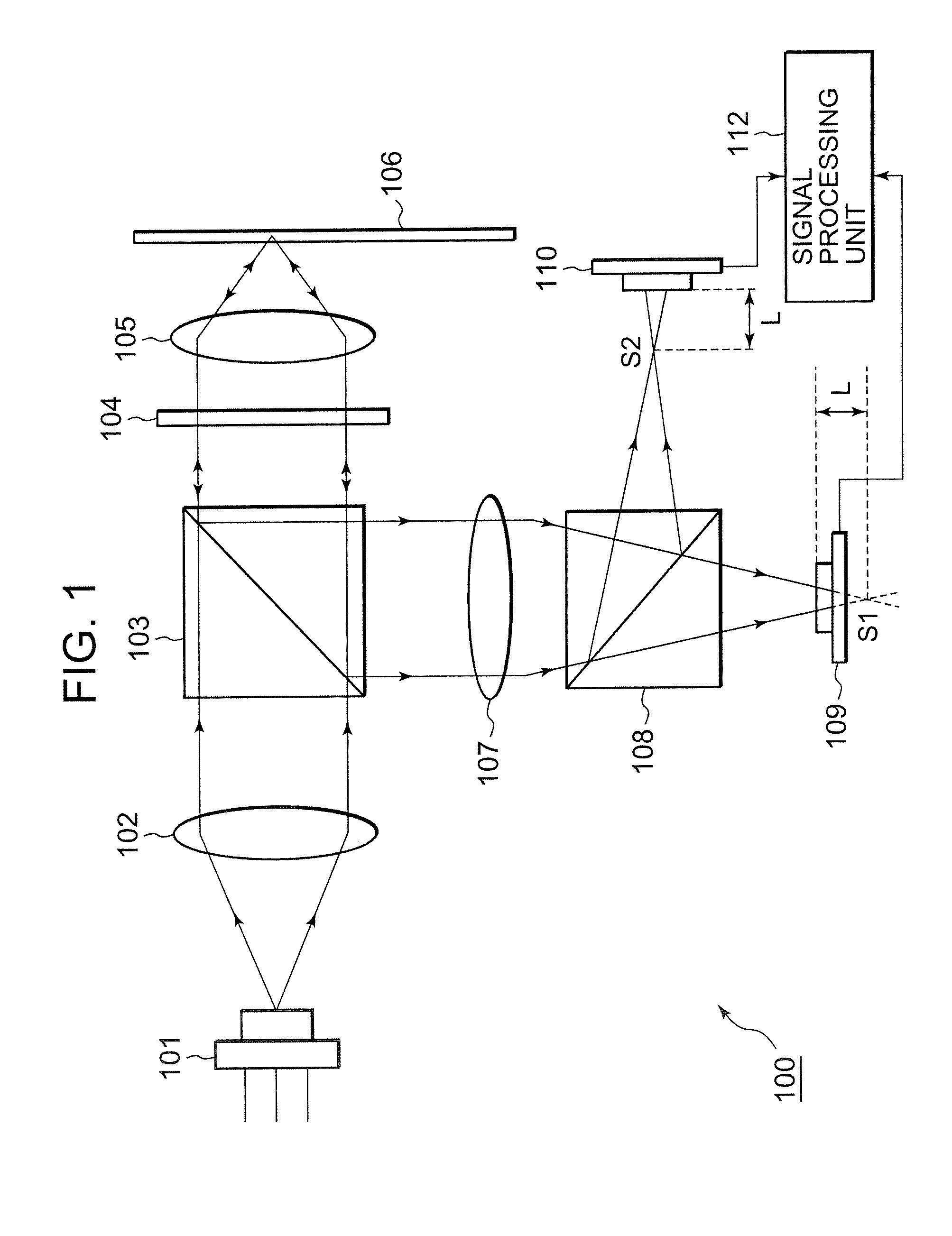
[0048]FIG. 1 shows the configuration of an optical pickup of an information processing apparatus according to a first embodiment of the present invention. As shown in FIG. 1, the optical pickup 100 includes a semiconductor laser 101 as a laser light source, and a collimator lens 102 and a polarization beam splitter (PBS) 103 are provided on the optical path of the output light from the semiconductor laser 101 in the order. Furthermore, a quarter wavelength plate 104 and an objective lens 105 are provided on the optical path on the light transmission side of the polarization beam splitter (PBS) 103 in the order.

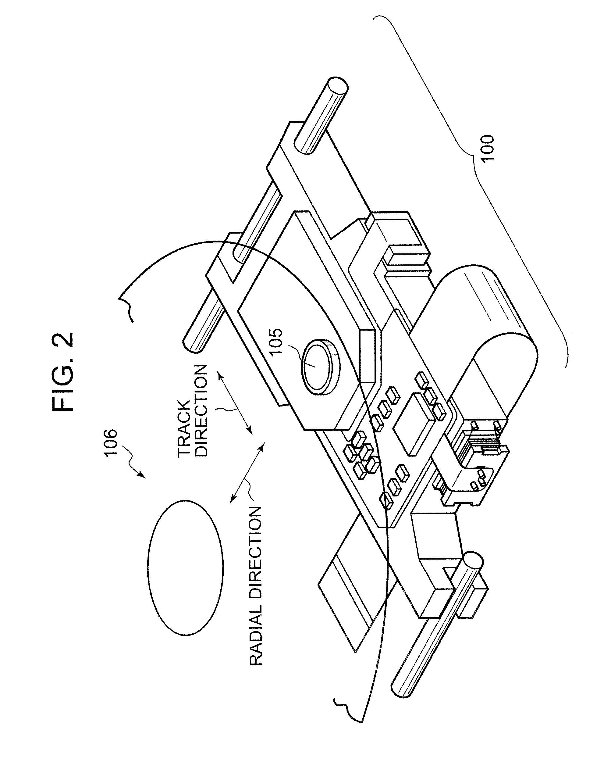
[0049]An optical disk 106 is located on the laser light output side of the objective lens 105. On the other hand, a condenser lens 107, a half mirror 108 and two photodetectors PD1109 and PD2110 that detect the return lights separated by the half mirror 108 are provided on the optical path on the return light side in the return path of the polarization beam splitter (PBS) 103....

second embodiment

[0094]Next, a description is given to a track error signal Tr calculation configuration capable of outputting an accurate track error signal even at the time of a focus error, i.e. at the time of the generation of a focus shift, by further improving the track error signal Tr calculation formula, i.e. Tr=(A−D)−ma{(B1+B2)−(C1+C2)}, which has been applied to the first embodiment mentioned above. In addition, as the apparatus configuration and the photodetector configuration, the same configurations as those described in the first embodiment with reference to FIGS. 1-3 are applied.

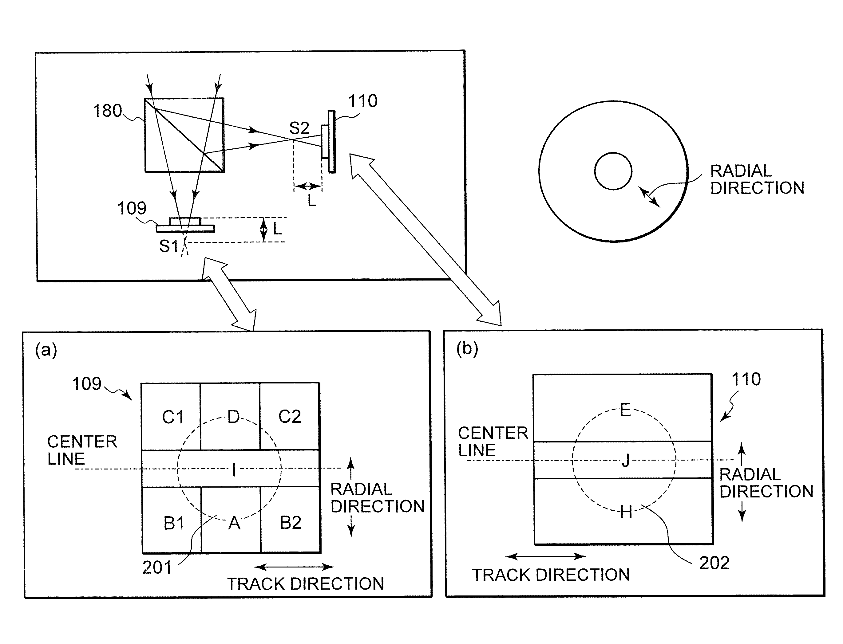
[0095]Also in the present embodiment, the focus error signal Fo and the track error signal Tr are acquired by using the photodiode PD1109 shown in the part (a) of FIG. 3, which is composed of seven divided light receiving elements A, B1, B2, C1, C2 D and I in total produced by being divided into three portions in a radial direction (in a radial direction of the disk) in a pattern symmetry to the center line, a...

third embodiment

[0118]Next, a description is given to a track error signal Tr calculation configuration enabling the output of a correct track error signal even at the time of the occurrence of a focus error, i.e. the occurrence of a focus shift, by changing the track error signal Tr calculation formula applied to the first embodiment mentioned above, i.e. Tr=(A−D)−ma{(B1+B2)−(C1+C2)}, in the manner different from that of the second embodiment. In addition, the apparatus configuration and the photodetector configuration similar to those described with reference to FIGS. 1-3 in the first embodiment are applied as those of the present embodiment.

[0119]The present embodiment also uses the photodetector PD1109 shown in the part (a) of FIG. 3, which is divided into three portions in a radial direction (a radial direction of the disk) in the pattern symmetry to the center line and the light receiving portions on both the ends other than the central portion I are severally divided into three portions (B1,...


PUM

PropertyMeasurementUnit
opticalaaaaaaaaaa
distanceaaaaaaaaaa
sizeaaaaaaaaaa

Abstract

An optical pickup for recording or reproducing information to an optical disk, includes: a first photodetector for detecting a return light from the optical disk, wherein the first photodetector is configured so that the first photodetector is divided into three portions in a radial direction corresponding to a radial direction of the optical disk and light receiving elements at both end portions in the radial direction are divided into three portions in substantially a track direction perpendicular to the radial direction, so that the first photodetector includes a light receiving element at a central portion in the radial direction and the three light receiving portions at each of both the end portions to be seven in total to output a light receiving element signal based on light reception of the return light as a track error signal generation signal.

Description

BACKGROUND OF THE INVENTION[0001]1. Field of the Invention[0002]The present invention relates to an optical pickup, an information processing apparatus and a signal processing method, and more particular to an optical pickup, an information processing apparatus and a signal processing method, each enabling accurate execution of the detection of a track error signal and a focus error signal.[0003]2. Description of the Related Art[0004]Recently, many optical disks (including magneto-optical disks) have been used as recording and reproducing media of digital data. The optical disks are, for example, a compact disk (CD), a mini disk (MD), a digital versatile disk (DVD) and the like.[0005]In data recording and reproducing in which such an optical disk is applied, the positional control of an optical pickup becomes necessary, and the detection of a return light from a disk read by the optical pickup is performed, for example, for tracking servo and focus servo. For example, the light spot...

Claims


Application Information

Patent Timeline
Patent Type & Authority Patents(United States)
IPC IPC(8): G11B7/00
CPCG02B27/144G02B27/283G02B27/40G11B7/0901G11B7/094G11B7/0943G11B7/131G11B7/0912G11B7/0945G11B7/09
Inventor ANZAWA, TAKUYA
Owner SONY CORP
Why Eureka
Try Eureka