
Multi-processor system verification circuitry

Active Publication Date: 2008-12-23
TEXAS INSTR INC
View PDF9 Cites 39 Cited by
  • Summary
  • Abstract
  • Description
  • Claims
  • Application Information

AI Technical Summary

Benefits of technology

[0011]The present invention provides significant advantages over the prior art. First, debugging the slave processor subsystem may be performed without understanding the implementation of the master processor subsystem in which the slave processor subsystem is embedded. Second, extraneous interactions are isolated from the slave processor system during verification procedures. Third, the external memory interface can be production tested at operating speed in the same way as an application is actually executed in the field, thereby increasing the fault coverage and capability for performance testing of the slave subsystem.

Problems solved by technology

First, debugging the slave processor subsystem may be performed without understanding the implementation of the master processor subsystem in which the slave processor subsystem is embedded.
Second, extraneous interactions are isolated from the slave processor system during verification procedures.

Method used


Image

  • Multi-processor system verification circuitry
  • Multi-processor system verification circuitry
  • Multi-processor system verification circuitry

Examples


Embodiment Construction

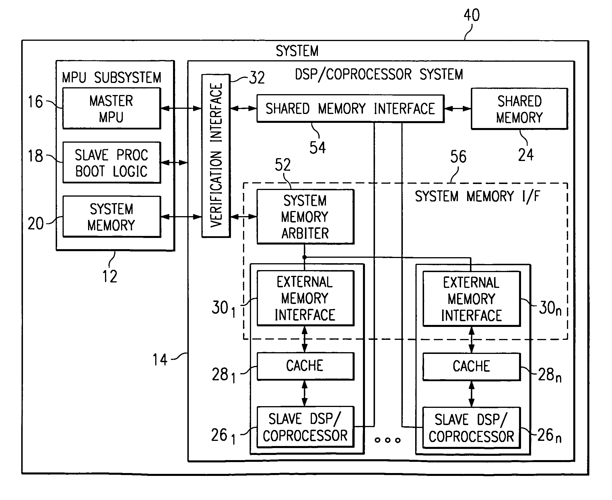
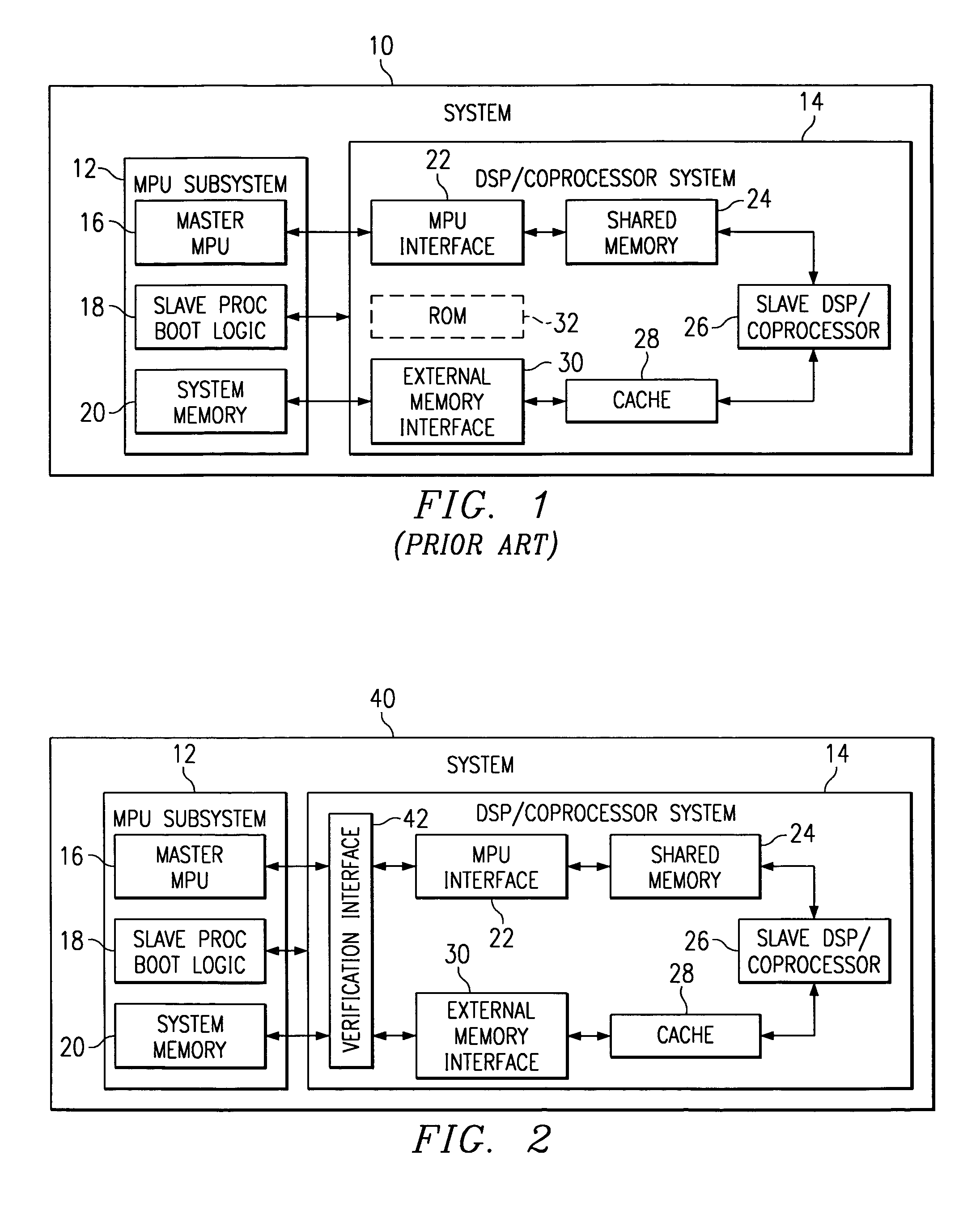
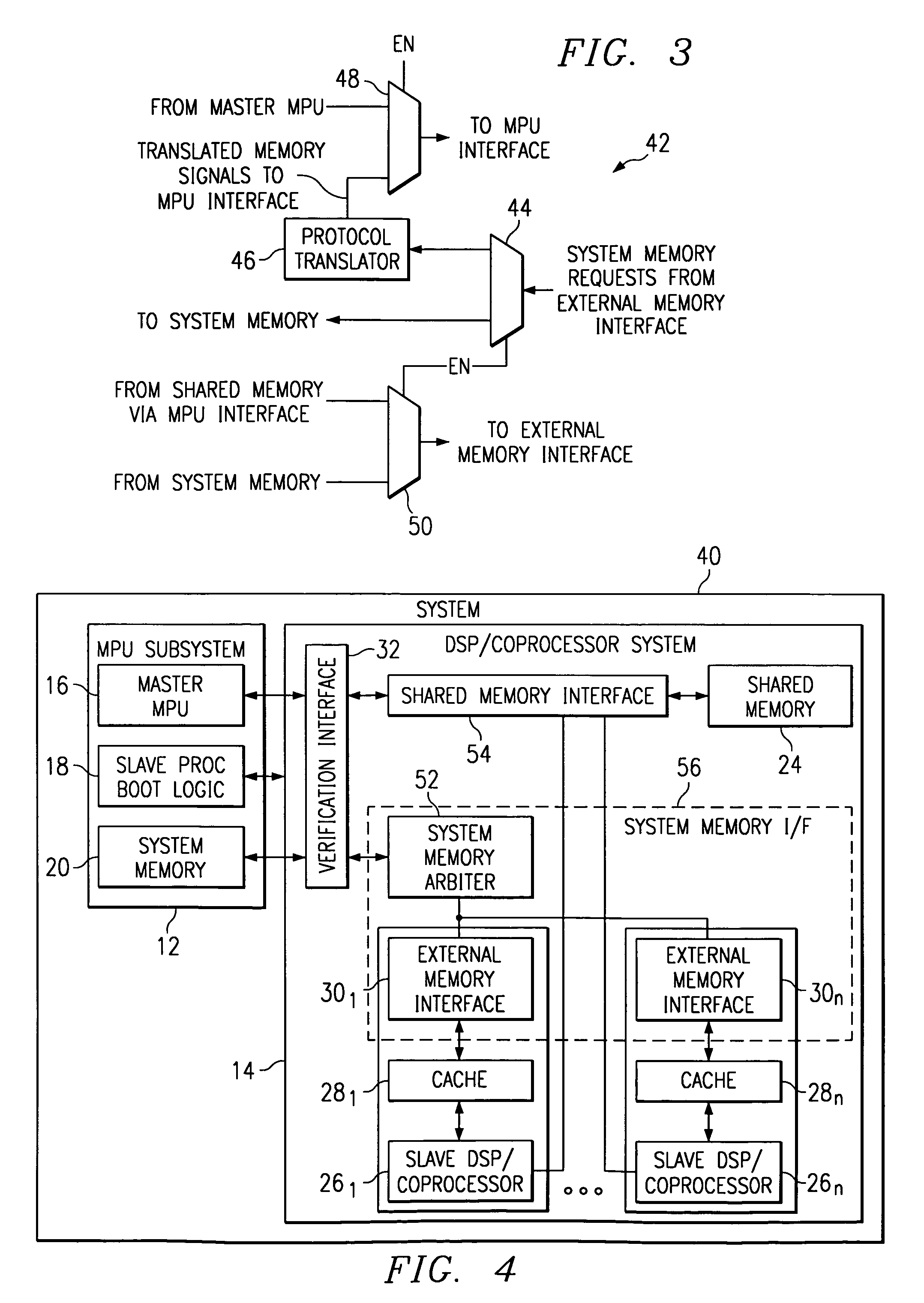
[0017]The present invention is best understood in relation to FIGS. 1-4 of the drawings, like numerals being used for like elements of the various drawings.

[0018]FIG. 1 illustrates a basic diagram of a multiprocessor system 10 including an MPU subsystem 12 and a DSP / Coprocessor subsystem 14. For purposes of illustration, it will be assumed that the MPU subsystem 12 and the DSP / Coprocessor subsystem 14 are proprietary designs by different companies, although this is not necessary for use of the present invention. MPU subsystem 12 includes a master MPU 16, slave processor boot logic 18 and system memory 20. DSP / Coprocessor subsystem 14 includes an MPU interface 22 for interfacing with the MPU subsystem 12, a shared memory 24 coupled to the MPU interface 22, a slave DSP / Coprocessor 26 coupled to the shared memory 24, a cache memory 28, and an external memory interface 30 coupled to the system memory 20 and cache 28. An optional ROM 32 may be used to store programs or data on the DSP / C...


PUM


Abstract

A multiprocessor system (40) includes a MPU subsystem (12), with master MPU (16) and shared memory (24), and a DSP / Coprocessor subsystem (14), with one or more slave DSP / Coprocessors (26). The system memory (20) is accessed by each DSP / Coprocessor subsystem (14) through a cache (28) and external memory interface (30). A verification interface (42) is used in verification mode to isolate the DSP / Coprocessor subsystem (14) from the MPU subsystem (12) and to translate system memory requests from the external memory interfaces (30) (through an arbiter (52), where multiple external memory interfaces are used) to a protocol which can be used to access the data from the shared memory (24).

Description

CROSS-REFERENCE TO RELATED APPLICATIONS[0001]Not ApplicableSTATEMENT OF FEDERALLY SPONSORED RESEARCH OR DEVELOPMENT[0002]Not ApplicableBACKGROUND OF THE INVENTION[0003]1. Technical Field[0004]This invention relates in general to integrated circuits and, more particularly, to a multiprocessor system verification circuit.[0005]2. Description of the Related Art[0006]Verifying the operation of an integrated circuit design is generally an extremely complicated procedure. This is especially true in the field of multi-processor designs, where a microprocessor unit is combined with other processor units, such as DSPs (digital signal processors), coprocessors or other microprocessor units.[0007]Verifying the operation of an integrated circuit may take several forms. One type of verification is generally referred to as “design debugging.” Debugging techniques are used to resolve weaknesses in the design of an integrated circuit. Another type of verification is generally referred to as “produc...

Claims


Application Information

Patent Timeline
IPC IPC(8): G06F15/173G06F11/267G06F11/27
CPCG06F11/2236G06F11/2242
Inventor ANDERSON, MARQUETTE JOHNBEDERR, HAKIM
Owner TEXAS INSTR INC
Learn More