
Mobile network that routes a packet without transferring the packet to a home agent server

Inactive Publication Date: 2008-12-09
MITSUBISHI ELECTRIC CORP
View PDF17 Cites 7 Cited by
  • Summary
  • Abstract
  • Description
  • Claims
  • Application Information

AI Technical Summary

Benefits of technology

[0014]The present invention is proposed to solve the above-mentioned problems, and it is therefore an object of the present invention to provide a mobile network that can prevent concentration of loads on one piece of equipment.

Problems solved by technology

A problem encountered with a prior art mobile network constructed as mentioned above is that loads are concentrated on an HA, as explained below.
A further problem arises in the scalability of the multiple IP networks because the load on each HA increases with an increase in the number of subnets.
Therefore, there causes a time delay different between the forward and backward directions of transmission because IP packets are passed through a route different depending on the direction of transmission of the IP packets, and this can result in the occurrence of trouble.

Method used


Image

  • Mobile network that routes a packet without transferring the packet to a home agent server
  • Mobile network that routes a packet without transferring the packet to a home agent server
  • Mobile network that routes a packet without transferring the packet to a home agent server

Examples


embodiment 1

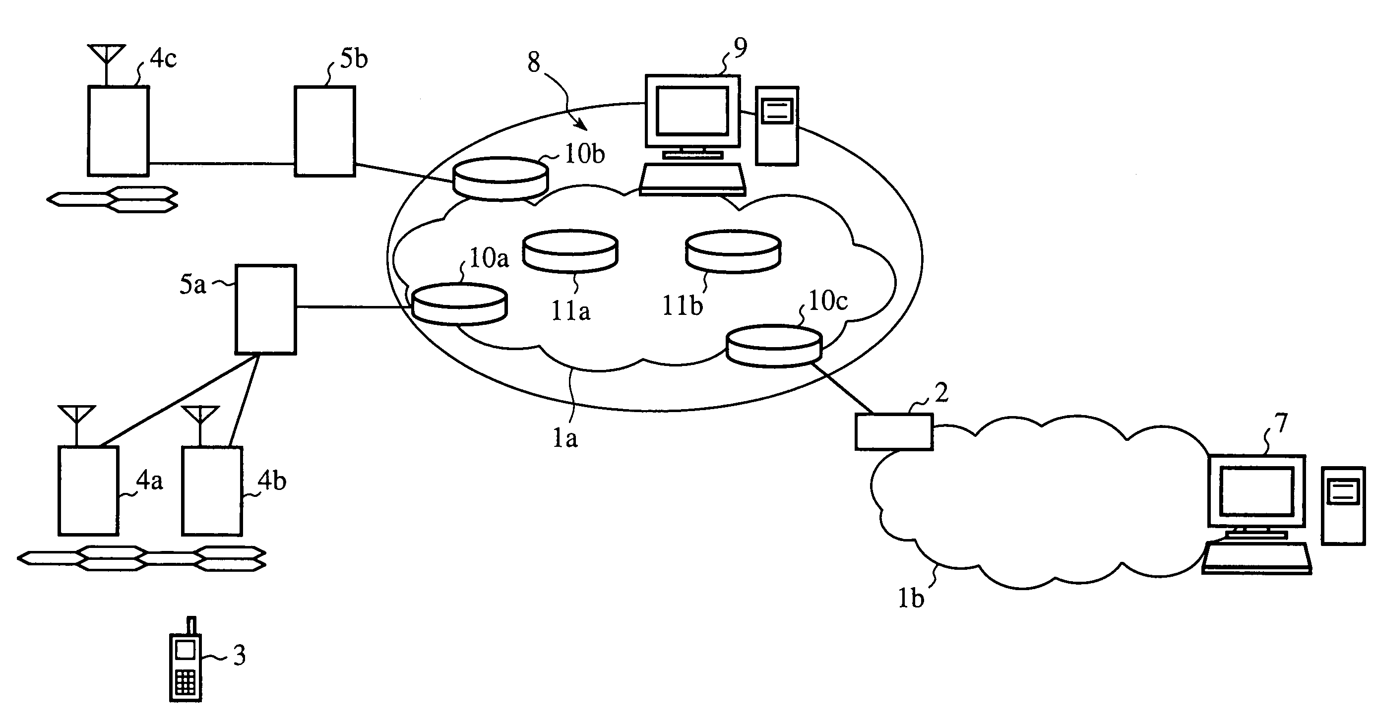
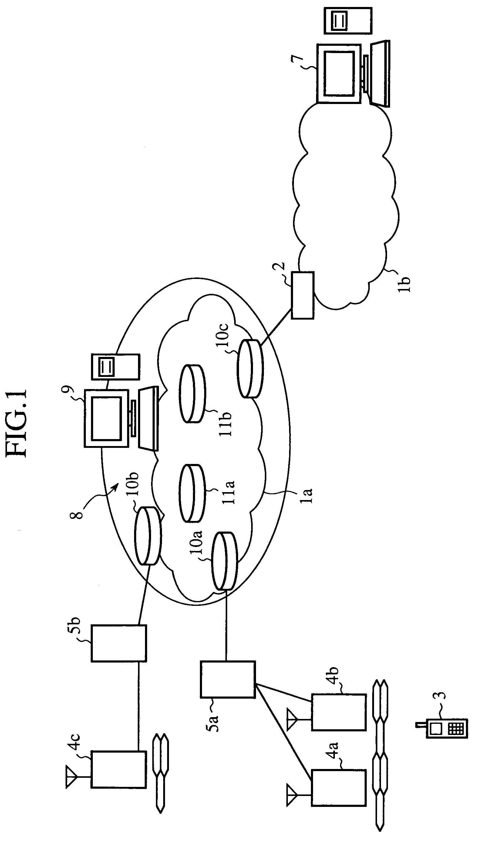
[0046]FIG. 1 shows multiple IP networks including a mobile network in accordance with embodiment 1 of the present invention. In the figure, reference numerals 1a and 1b denote IP networks, reference numeral 2 denotes a network gateway, reference numeral 3 denotes a mobile terminal, reference numerals 4a, 4b, and 4c denote base stations, reference numerals 5a and 5b denote foreign agents (FAs), reference numeral 7 denotes a communication node (CN), reference numeral 8 denotes a virtual home agent (HA), reference numeral 9 denotes a home agent (HA) server, reference numerals 10a to 10c denote IP tunnel routers, and reference numerals 11a and 11b denote routers.

[0047]The IP networks 1a and 1b are different IP networks each of which partially constitutes multiple IP networks, and operate according to different protocols. Each of the IP networks 1a and 1b has a plurality of routers. It is assumed that the IP network 1b shown in the figure is the Internet. The IP networks 1a and 1b are co...

embodiment 2

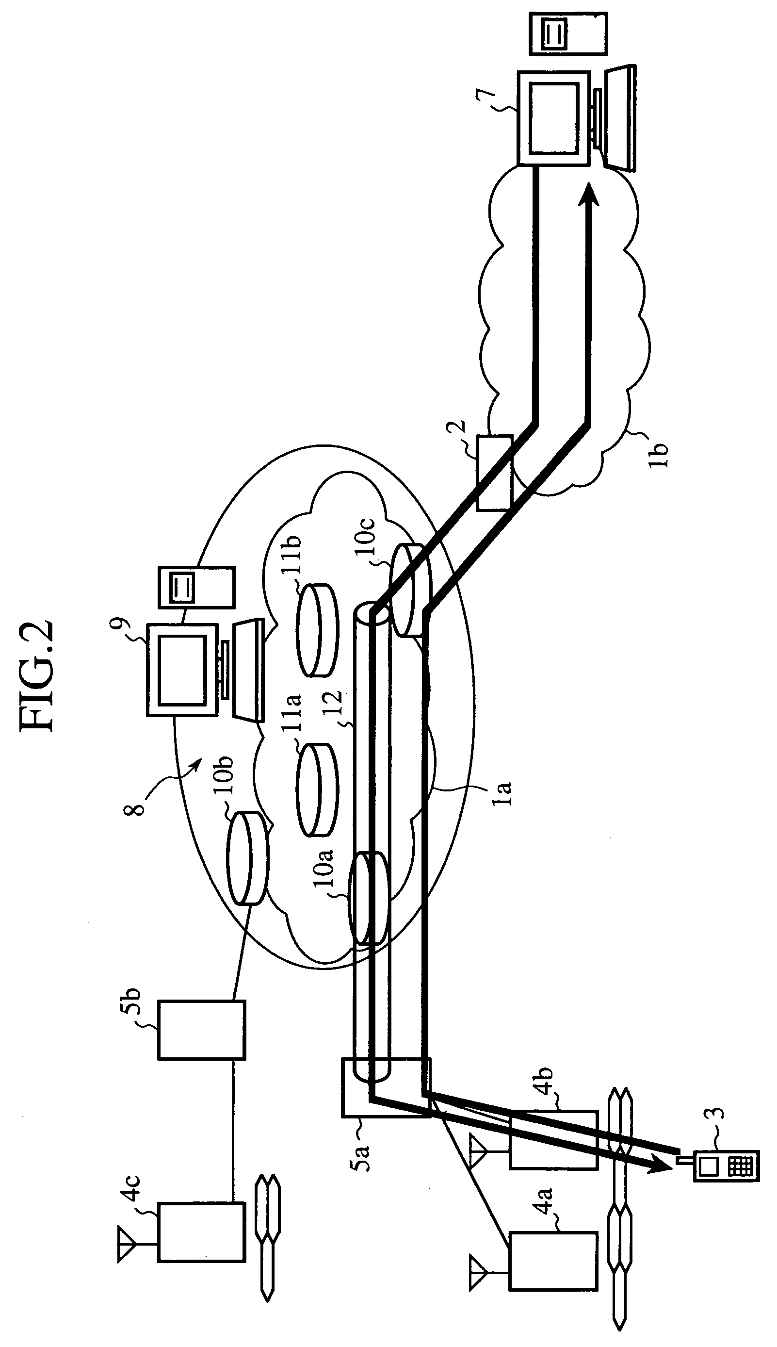
[0079]FIG. 6 shows a flow of user data between a mobile terminal 3 and a CN 7 in a mobile network in accordance with embodiment 2 of the present invention. The mobile network in accordance with embodiment 2 of the present invention and entire multiple IP networks can be the same as those as shown in FIG. 1. An HA server 9, a plurality of IP tunnel routers 10a to 10c, FAs 5a and 5b have additional functions described later, respectively.

[0080]In FIG. 6, reference numeral 13 denotes a virtual reverse IP tunnel extending from the FA 5a to the IP tunnel router 10a. In accordance with this embodiment 2, during backward-direction communications from the mobile terminal 3 to the CN 7, the reverse IP tunnel 13 via which encapsulated IP packets are transmitted is used as a route from an FA (e.g., the FA 5a) to an IP tunnel router (e.g., the IP tunnel router 10a). Other operations, i.e., forward-direction communications from the CN7 to the mobile terminal 3 are conducted in the same way as ex...

embodiment 3

[0099]FIG. 9 shows multiple IP networks having a mobile network in accordance with embodiment 3 of the present invention. In the figure, reference numeral 20 denotes an MPLS (MultiProtocol Label Switching) network, and reference numerals 20a to 20c denote IP tunnel routers.

[0100]In the multiple IP networks of FIG. 9, the IP network 1a of FIG. 1 is replaced by the MPLS network 20, and the plurality of IP tunnel routers 10a to 10c are replaced by the plurality of IP tunnel routers 20a to 20c. Other nodes are the same as those as shown in FIG. 1. A virtual HA 8 is provided with an HA server 9 and the plurality of IP tunnel routers 20a to 20c.

[0101]Next, a description will be made as to an operation of the mobile network in accordance with embodiment 3 of the present invention. Basically, each node as shown in FIG. 9 operates in the same way that a corresponding node of above-mentioned embodiment 1 or 2 does. In addition, in order to ensure QoS (Quality of Service) in the home network ...


PUM


Abstract

A mobile network that is a subnet that partially constitutes multiple IP networks includes a home agent server for managing identifiers of a plurality of mobile terminals each of which joins the mobile network, and a plurality of IP tunnel routers. When a mobile terminal moves from the subnet to another subnet that partially constitutes the multiple IP networks, the home agent server accepts destination information necessary for transmission of IP packets to the mobile terminal from the mobile terminal, and delivers IP tunnel setting information indicating the mobile terminal and the destination information to the plurality of IP tunnel routers. When then receiving an IP packet destined for the mobile terminal, each of the plurality of IP tunnel routers transfers the IP packet to the mobile terminal based on the IP tunnel setting information without making the IP packet go through the home agent server.

Description

FIELD OF THE INVENTION[0001]The present invention relates to a mobile network.BACKGROUND OF THE INVENTION[0002]Mobile IP is proposed as a method of, when a mobile terminal having an IP (internet protocol) address moves from a subnet that partially constitutes multiple IP networks to another subnet that partially constitutes the multiple IP networks, making it possible for the mobile terminal to maintain communications without interrupting sessions. The mobile IP is defined by RFC (Request for Comment: Document including information about the Internet) 2002 of IETF (Internet Engineering Task Force: Internet technology special investigation committee).[0003]An example of a mobile network using the mobile IP is shown in FIG. 17. In the figure, reference numerals 1a and 1b denote IP networks, reference numeral 2 denotes a network gateway, reference numeral 3 denotes a mobile terminal, reference numerals 4a, 4b, and 4c denote base stations, reference numeral 5 denotes a foreign agent (FA...

Claims


Application Information

Patent Timeline
IPC IPC(8): G06F13/00H04L29/06
CPCH04L29/06H04W8/04H04W8/26H04W28/18H04W36/02H04W40/34H04W80/04H04W88/14H04L63/029H04L63/166H04L9/40
Inventor SHIMIZU, KEIICHI
Owner MITSUBISHI ELECTRIC CORP
Learn More