Nondestructive optical technique for simultaneously measuring optical constants and thickness of thin films

a technology of optical constants and thin films, applied in the field of optical measuring systems and methods, can solve the problems of inability to measure optical constants, inability to decouple or measure thin films independently, coupled optical constants and thicknesses, etc., and achieve the effect of minimizing the merit function

Active Publication Date: 2008-12-09
BRUKER NANO INC
View PDF12 Cites 16 Cited by
  • Summary
  • Abstract
  • Description
  • Claims
  • Application Information

AI Technical Summary

Benefits of technology

[0016]The final step is to determine the thicknesses and coefficients of the dispersion formula (optical constants) of the unknown layers. Nonlinear global optimization algorithms may be used in the final step to minimize the merit function (loss function or error function) of experimental and theoretical data.

Problems solved by technology

However, for very thin films (on the order of a few atomic layers), these methods are not capable of measuring the optical constants (n and k) and thickness independently, and at times yield inaccurate results.
A major disadvantage of these conventional methods is that the optical constants and thickness are coupled and for very thin films they cannot be decoupled or measured independently.

Method used


Image

  • Nondestructive optical technique for simultaneously measuring optical constants and thickness of thin films
  • Nondestructive optical technique for simultaneously measuring optical constants and thickness of thin films
  • Nondestructive optical technique for simultaneously measuring optical constants and thickness of thin films

Examples


Embodiment Construction

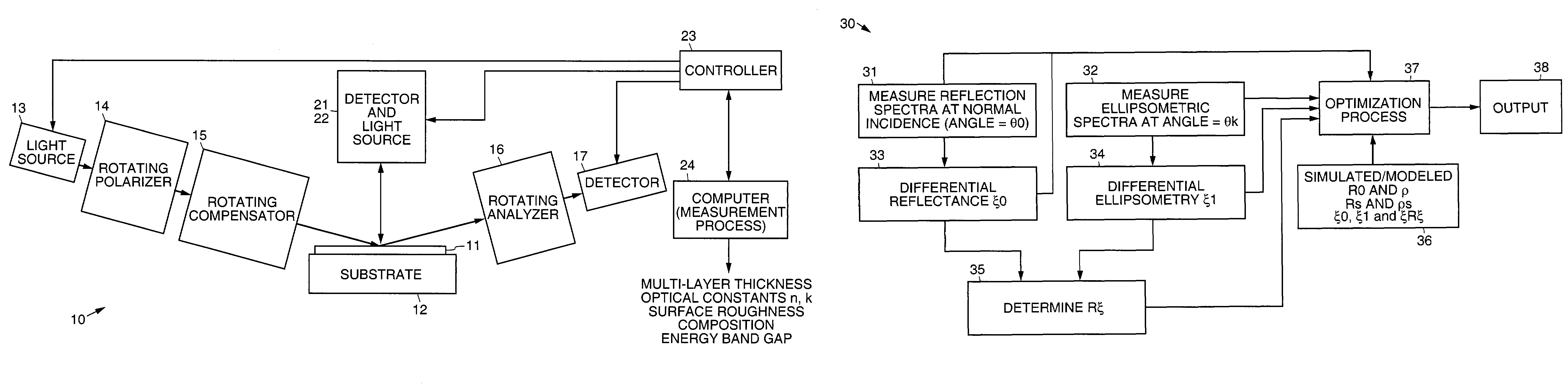
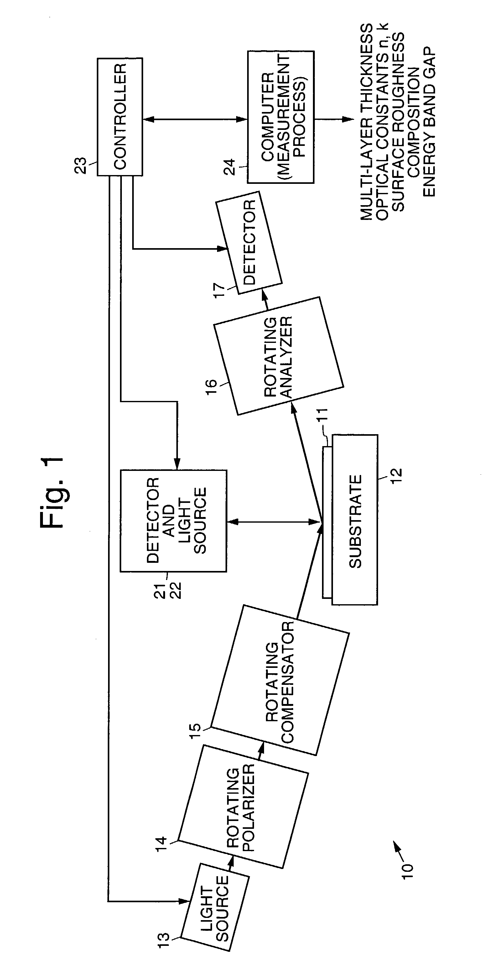
[0025]Referring to the drawing figures, FIG. 1 illustrates an exemplary measurement system 10 in accordance with the principles of the present invention. The exemplary measurement system 10 comprises a first light source 13 that emits light that is incident at an oblique angle upon a thin film 11 disposed on a substrate 12. The light that is emitted by the first light source 13 passes through a (fixed or rotating) polarizer 14 and an optional (fixed or rotating) compensator 15 (fixed or rotating retarder 15) prior to impinging upon the thin film 11. The rotating polarizer 14 operates to linearly polarize the incident beam. The optional (fixed or rotating) compensator 15 operates to elliptically polarize the incident beam.

[0026]The light that is emitted from the first light source 13 and reflected from the thin film 11 passes through a (fixed or rotating) analyzer 16 and is detected by a first detector 17 that is disposed at an oblique angle that is complementary to the oblique angle...


PUM


Abstract

Optical systems and methods that simultaneously measure optical constants (n, k) and thickness of thin films. The systems and methods use of differential polarimetry (differential analysis of spectroscopic multi-angle reflection and ellipsometric data) to measure optical constants (n k) and thickness of ultra-thin films.

Description

BACKGROUND[0001]The present invention relates to optical measuring systems and methods, and more particularly to nondestructive optical systems and methods for simultaneously measuring optical constants (n, k) and thickness of thin films.[0002]There are several known methods for determining the optical constants and thickness of thin films. One conventional method is disclosed in “Handbook of Optical Constants of Solids”, edited by E. D. Palik (academic Press, N.Y., 1985). This method measures normal-incidence reflectance and transmittance over a wide spectral range.[0003]Another conventional method is disclosed in “Handbook of Optical Constants of Solids II”, edited by E. D. Palik (Academic Press, N.Y., 1991). This method measures R and T for normal and oblique angles of incidence (45′; 60′) for the polarizations TE and TM, over a wide spectral range.[0004]Another conventional method is disclosed by O. S. Heavens in “Physics of Thin Films”, Vol. 2, edited by G. Hass and R. E. Thum ...

Claims


Application Information

Patent Timeline
Patent Type & Authority Patents(United States)
IPC IPC(8): G01J4/00
CPCG01B11/0641G01B11/303G01N21/211G01N21/41G01N2021/213
Inventor ZAWAIDEH, EMAD
Owner BRUKER NANO INC
Why Eureka
Try Eureka