
Vehicle with a supply unit

a technology of supply unit and vehicle, which is applied in the direction of machines/engines, electrochemical generators, combustion air/fuel air treatment, etc., can solve the problems of marked degradation of storage efficiency, and achieve the effect of improving storage of fuel gas

Inactive Publication Date: 2008-11-25
ROBERT BOSCH GMBH
View PDF11 Cites 53 Cited by
  • Summary
  • Abstract
  • Description
  • Claims
  • Application Information

AI Technical Summary

Benefits of technology

This solution enables nearly complete evacuation of the fuel gas reservoir, increasing storage efficiency and reducing the required space, especially in low-pressure systems, by adjusting the storage volume according to the fuel gas quantity and utilizing available pressures for efficient filling and evacuation.

Problems solved by technology

With the related art, in the case of which compressed gas reservoirs or metal-hydride reservoirs having a constant storage volume are used, a considerable quantity of fuel gas still remains in the gas reservoir in the evacuated state, which markedly degrades the efficiency of storage.

Method used


Image

  • Vehicle with a supply unit
  • Vehicle with a supply unit
  • Vehicle with a supply unit

Examples


Embodiment Construction

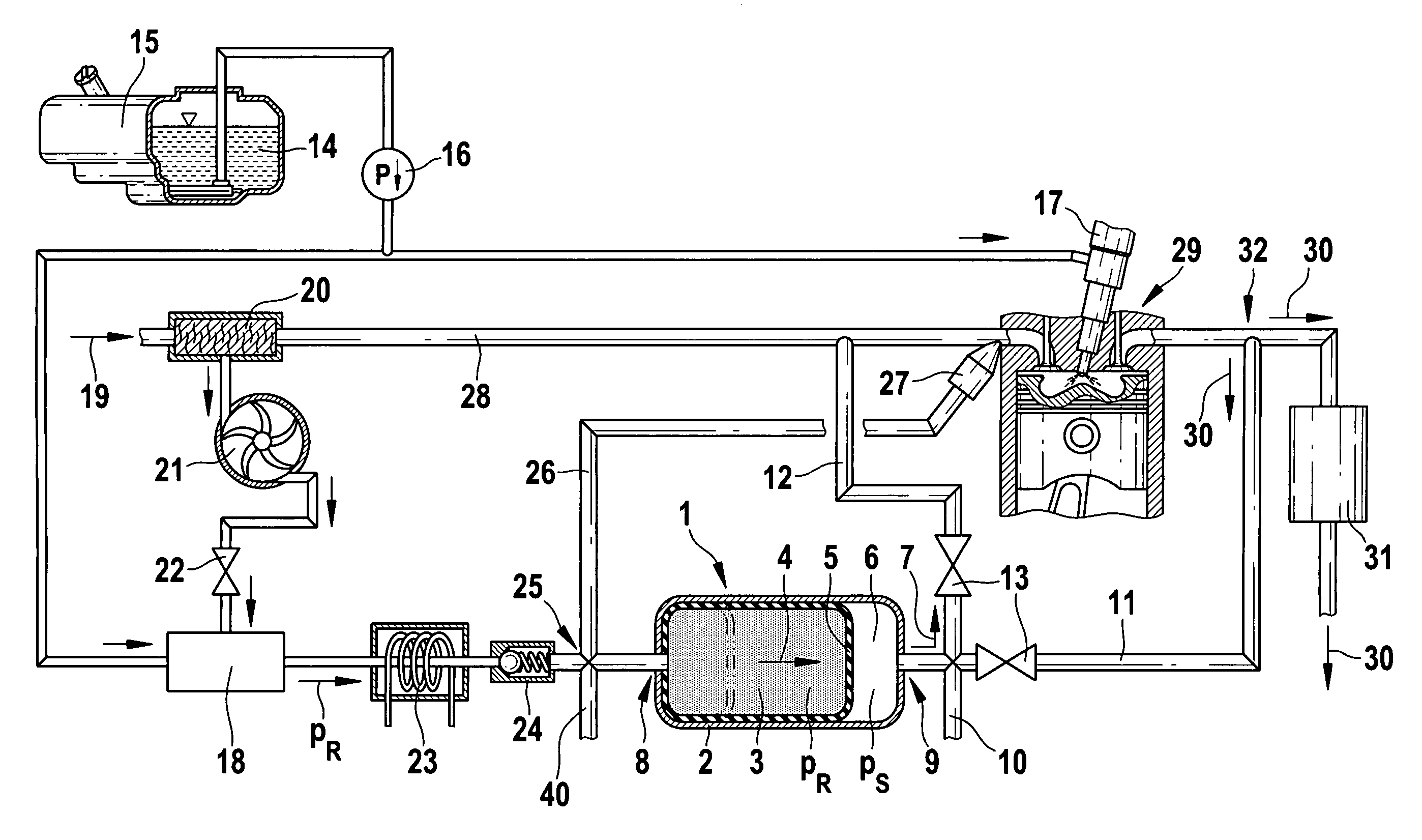
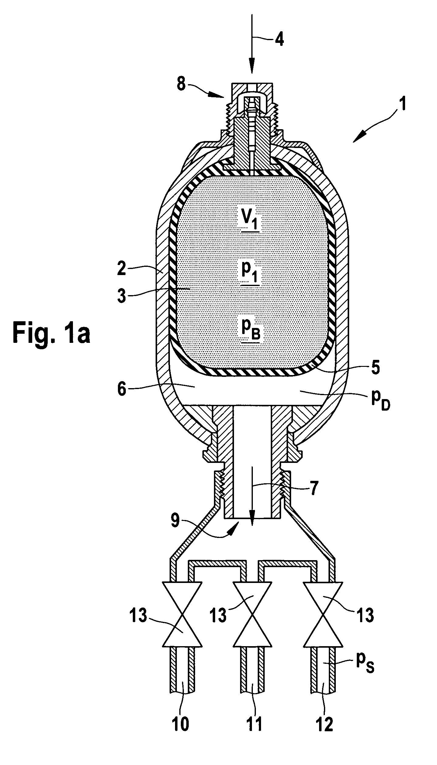
[0038]A gas reservoir 1 according to the present invention is shown schematically in FIG. 1. Gas reservoir 1 includes a housing 2, which is configured, e.g., as a pressure vessel housing 2. The storage volume 3 for storage of a fuel gas 4 is located in gas reservoir 1.

[0039]A bladder 5, essentially, for delineating storage volume 3 is provided between fuel gas 4 and housing 2 of gas reservoir 1. In the exemplary embodiment of the present invention shown, bladder 5 is designed as an elastically expandable bladder.

[0040]In addition to storage volume 3 for fuel gas 4, gas reservoir 1 also includes a second storage volume 6 for a compressed gas 7. Compressed gas 7 is delineated by housing 2 and bladder 5.

[0041]Gas reservoir 1 includes a first opening 8 for fuel gas 4 and a second opening 9 for compressed gas 7. The two openings are provided for the inflow and outflow of corresponding gases 4, 7. In principle, separate inflow and outflow openings can also be provided.

[0042]A filling stat...


PUM


Abstract

A vehicle has a fuel system operative to chemically reform a fuel gas, a supply unit for supplying the fuel system with the fuel gas, and a gas reservoir provided with a storage volume for an intermediate storage of the fuel gas, the storage volume having a size that is changeable.

Description

BACKGROUND OF THE INVENTIONCROSS-REFERENCE[0001]The invention described and claimed herein below is also described in DE 10 2004 063 071.2, filed Dec. 28, 2004. This German Patent Application. whose subject matter is incorporated here by reference, provides the basis for a claim of priority of invention under 35 U.S.C. 119 (a)-(d).[0002]The present invention relates to a vehicle with a supply unit for supplying a fuel system, in particular an internal-combustion engine, a fuel cell unit, a catalytic converter and / or the like, with a fuel gas.[0003]Modern internal-combustion engines, in particular gasoline engines for vehicle propulsion, are equipped with catalytic exhaust-gas converters. Particularly during cold starts, however, even higher quantities of unburned hydrocarbons are emitted, e.g., due to incomplete fuel evaporation or fuel condensation on the still-cold cylinder walls, but also due to the fact that the temperature of the catalytic converter is still too low.[0004]Addin...

Claims


Application Information

Patent Timeline
Patent Type & Authority Patents(United States)
IPC IPC(8): F01N3/00
CPCB60K15/03006B60K15/10C01B3/386F01N3/206F02D19/081F02M21/0224F02M27/02F02M37/0064H01M8/04082H01M8/0612F02D19/0644F02D19/0665F02D19/0671F02D19/0678F02D19/022C01B2203/0261C01B2203/066F01N2240/30F01N2610/04F01N2610/11F02D33/006F17C2227/0192H01M2250/20Y02T10/36Y02T90/32Y02T10/32F02D19/0692Y02E60/50Y02A50/20Y02T10/30Y02T90/40
Inventor ALLGEIER, THORSTENFAYE, IANGOTTWICK, ULRICHGRAEHN, JAN-MICHAEL
Owner ROBERT BOSCH GMBH
Learn More