Exhaust purifier for diesel engine

a technology for exhaust purifiers and diesel engines, which is applied in the direction of machines/engines, electric control, speed sensing governors, etc., can solve the problems of clogging the filter, lowering the output of the diesel engine, and the exhaust purifier may not be sufficiently heated

Inactive Publication Date: 2008-11-25
TOYOTA IND CORP
View PDF12 Cites 9 Cited by
  • Summary
  • Abstract
  • Description
  • Claims
  • Application Information

AI Technical Summary

Benefits of technology

[0006]The present invention provides an exhaust purifier for a diesel engine that ensures a predetermined amount of intake air amount when the filter temperature increase control is being executed under a low pressure environment.
[0007]One aspect of the present invention is an exhaust purifier for a diesel engine having an exhaust passage. The exhaust purifier includes a filter arrangeable in the exhaust passage of the diesel engine. A first detector detects atmospheric pressure. A controller controls the engine speed of the diesel engine. A second detector detects the engine speed of the diesel engine. The controller compares an intake air amount, which is based on the atmospheric pressure detected by the first detector and the engine speed detected by the second detector, with a reference air amount during regeneration of the filter. The controller performs idle-up for increasing the idle speed of the diesel engine when the intake air amount is less than the reference air amount.

Problems solved by technology

However, deposition of the PM clogs the filter and lowers the output of the diesel engine.
Thus, the exhaust purifier may not be sufficiently heated.
However, when driving the vehicle while regenerating the exhaust purifier, if the engine starts to idle, the intake air decreases.
As a result, for example, the balance between the heat generated by PM combustion and the heat absorbed by air cannot be maintained thereby causing overshoot (hereinafter referred to as deceleration OT).
However, under a low pressure environment, the intake air amount may not be ensured even by correcting the opening of the throttle valve.

Method used


Image

  • Exhaust purifier for diesel engine
  • Exhaust purifier for diesel engine
  • Exhaust purifier for diesel engine

Examples


Embodiment Construction

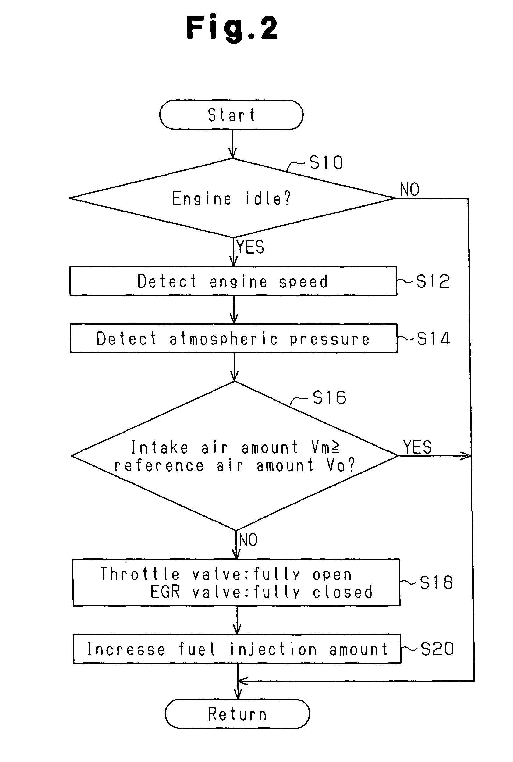
[0015]A preferred embodiment of the present invention will now be described with reference to FIGS. 1 and 2.

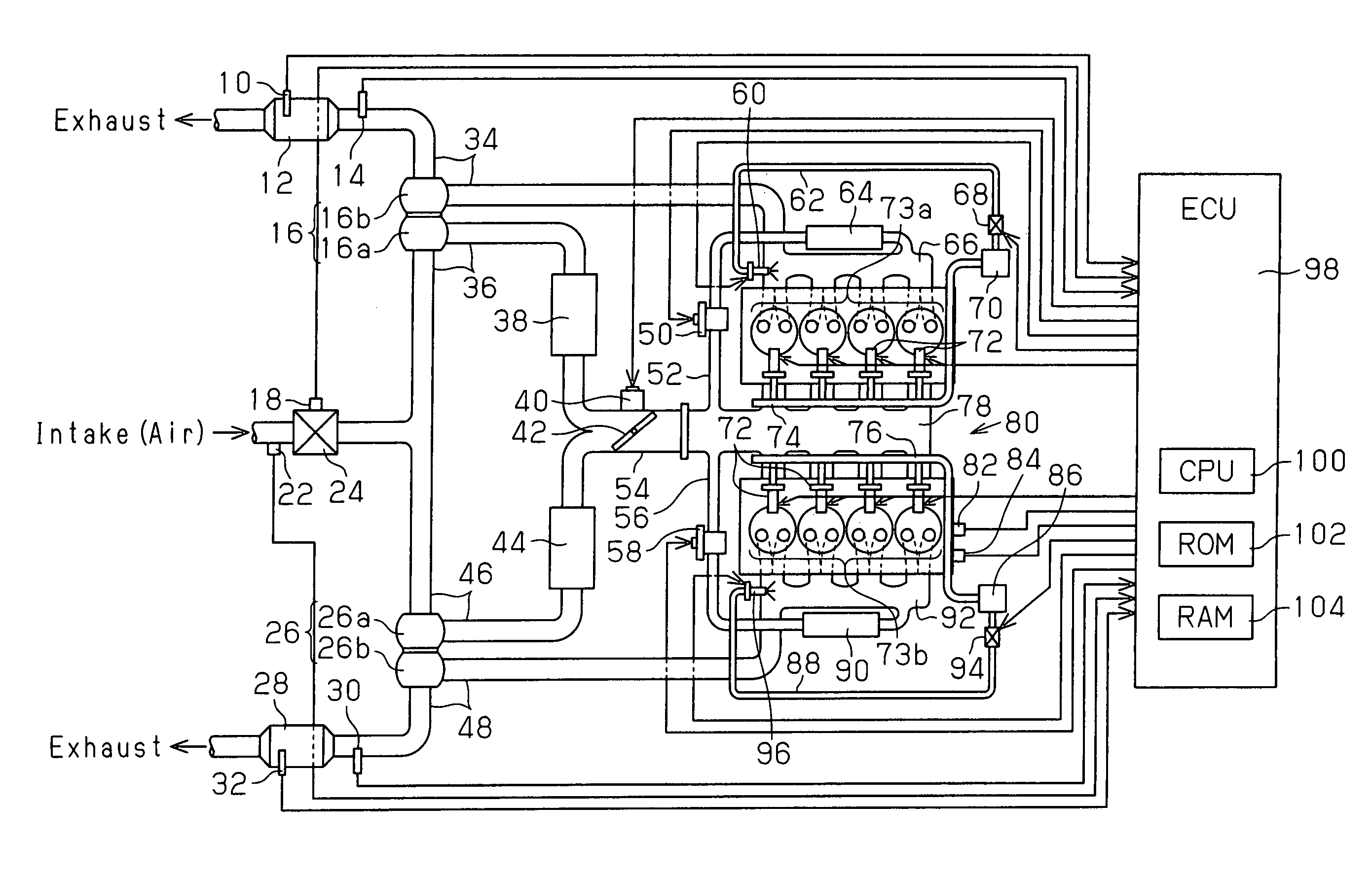
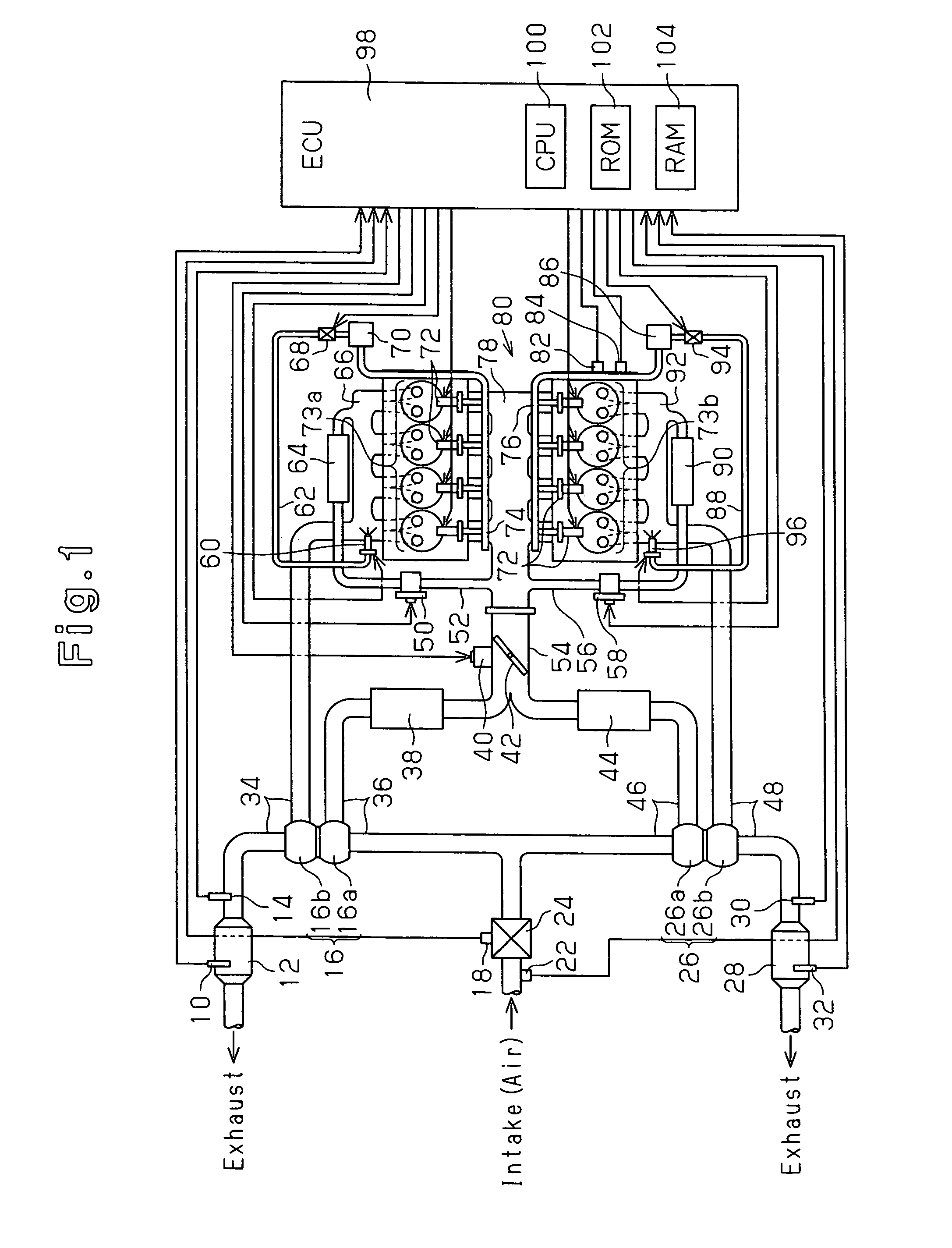
[0016]As shown in FIG. 1, an engine system includes a diesel engine 80 and an electronic control unit (ECU) 98 for electronically controlling the diesel engine 80.

[0017]The diesel engine 80 is an eight cylinder engine having two cylinder banks 73a and 73b. Each of the cylinder banks 73a and 73b include four cylinders arranged along a straight line. The diesel engine 80 further includes an intake manifold 78 and two exhaust manifolds 66 and 92.

[0018]A fuel injection nozzle (injectors) 72, which functions as a fuel injection valve for injecting fuel into a combustion chamber, is attached to each cylinder. A coolant temperature sensor 84 for detecting the coolant temperature and an engine speed sensor 82, which functions as a second detector for detecting the engine speed, are attached to the diesel engine 80. For example, a resolver or an encoder may be used as the engine speed ...


PUM


Abstract

A controller for an exhaust purifier performs idle-up to increase the idle speed of a diesel engine when an intake air amount, which is based on the atmospheric pressure and the engine speed, is less than a reference air amount of when a throttle valve is completely open and an EGR valve is completely closed during the regeneration of the filter. The controller performs idle-up by increasing the amount of fuel injected from the fuel injection valves of the diesel engine.

Description

BACKGROUND OF THE INVENTION[0001]The present invention relates to an exhaust purifier for a diesel engine.[0002]The exhaust gas (hereinafter referred to as “exhaust”) emitted from a diesel engine contains particulate matter (hereinafter referred to as PM). The use of a particulate filter (hereinafter referred to as filter) in an exhaust system for elimination of the PM is well known in the prior art. However, deposition of the PM clogs the filter and lowers the output of the diesel engine. In order to resolve the problem of PM deposition, the filter is heated to a predetermined temperature (approximately 650° C. (hereinafter referred to as regeneration temperature)) to oxidize (burn) the PM deposited in the filter and regenerate the filter.[0003]The amount of air actually drawn into the engine decreases at high altitudes due to the low air density. In such a case, the amount of fuel injected into the engine is controlled so as to be reduced. This lowers the temperature of the exhaus...

Claims


Application Information

Patent Timeline
Patent Type & Authority Patents(United States)
IPC IPC(8): F01N3/00
CPCF02D31/008F02D41/029F02D41/083F02D41/182F02D41/38F02M25/0711F02M25/0732F02B29/0412F02D2041/0022F02D2200/0402F02D2200/703F02M26/08F02M26/24
Inventor MIZUGUCHI, KEIICHI
Owner TOYOTA IND CORP
Why Eureka
Try Eureka