
Generation of engineering change order (ECO) constraints for use in selecting ECO repair techniques

a technology of engineering change order and constraints, applied in the direction of cad circuit design, program control, instruments, etc., can solve the problems of difficult correction of crosstalk induced violations using prior art methods known to inventors, and undesirable electrical interactions between paths

Active Publication Date: 2008-11-18
SYNOPSYS INC
View PDF4 Cites 181 Cited by
  • Summary
  • Abstract
  • Description
  • Claims
  • Application Information

AI Technical Summary

Problems solved by technology

Crosstalk is an undesirable electrical interaction between two or more physically adjacent nets due to capacitive cross-coupling.
When the slack of a path is negative, the path has a timing violation.
Correction of crosstalk induced violations using prior art methods known to inventors is difficult and often requires significant manual intervention across several iterations between the crosstalk analysis tool and the place and route tool.
If the static timing and noise analysis tool finds any violations in the modified design then the process is repeated, requiring significant human effort.
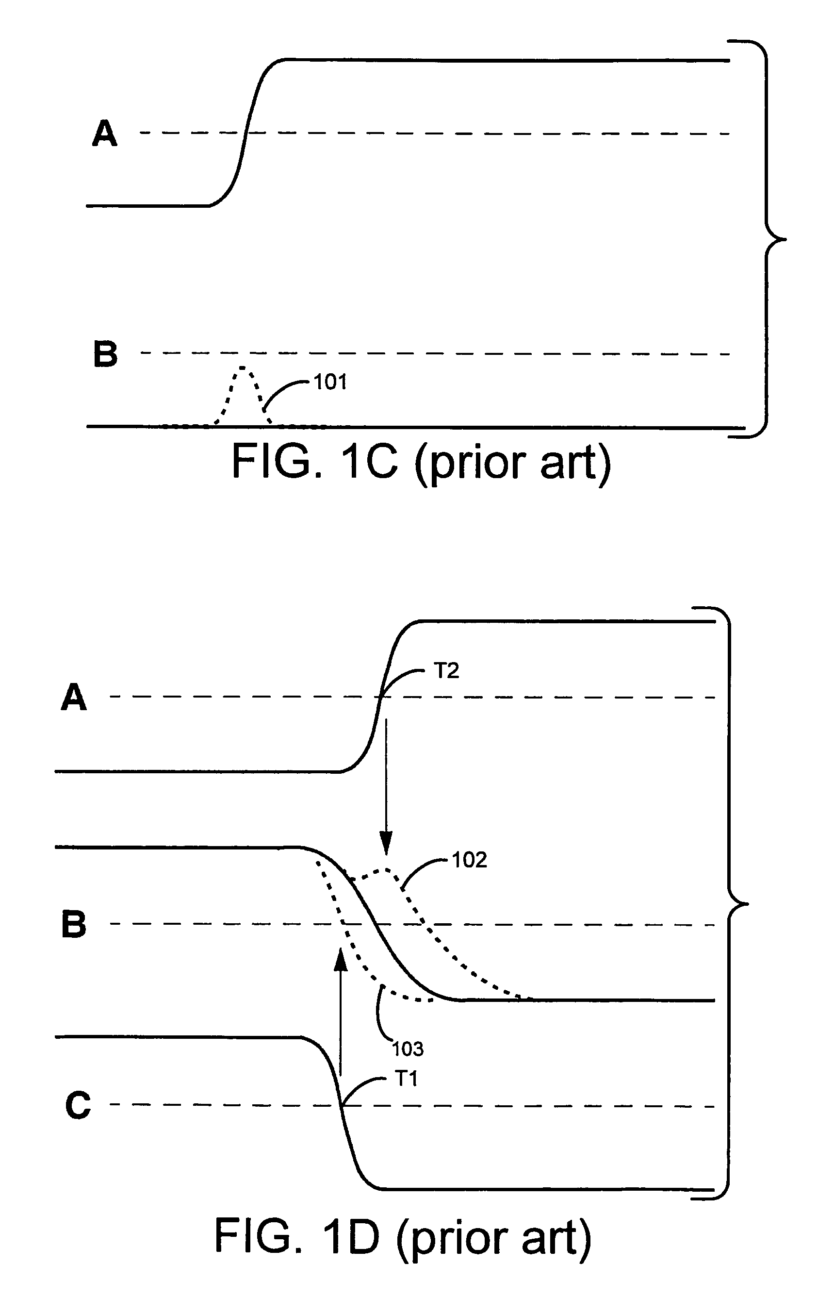
Specifically, sizing up a victim driver cell (see bottom net in FIG. 1F) reduces its drive / holding resistance resulting in smaller crosstalk delay.
This causes a large crosstalk delay for the aggressor net which in turn may create a new timing violation.
Moreover, even if it appears during crosstalk analysis, that sizing up a cell is feasible, it is possible that the place and route tool is unable to size up the same cell, e.g. if there is no physical space available for upsizing in its neighborhood.
Hence, these types of problems cause multiple iterations of ECO based on human input and / or trial-and-error which may not necessarily converge, especially in case of large IC designs.

Method used


Image

  • Generation of engineering change order (ECO) constraints for use in selecting ECO repair techniques
  • Generation of engineering change order (ECO) constraints for use in selecting ECO repair techniques
  • Generation of engineering change order (ECO) constraints for use in selecting ECO repair techniques

Examples


Embodiment Construction

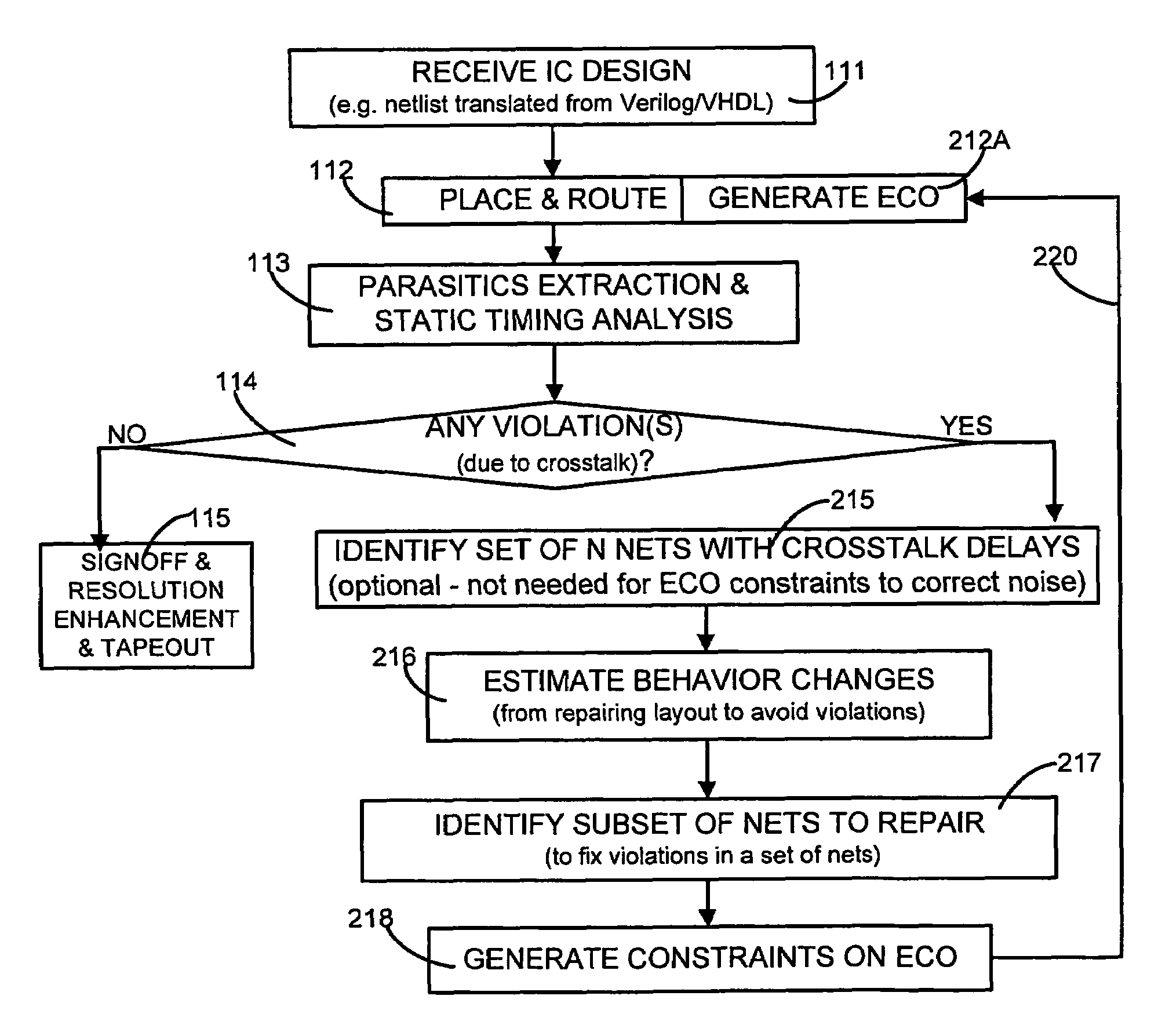
[0030]A computer 150 (FIG. 9A) is programmed in several illustrative embodiments of the invention to automatically perform static timing and / or noise analysis on an IC design in the form of a netlist, to estimate timing and / or noise behavior of a layout for the netlist obtained from a place and route operation (which places blocks of circuitry and routes wires therebetween), and to identify at least one violation by the behavior of a corresponding requirement thereon, such as setup time, hold time or bump height in a quiescent net.

[0031]Timing violations are typically identified (at the end of static timing analysis) as a list of endpoints of corresponding paths in the netlist. The computer 150 then identifies one or more victim nets that are located in a fanin cone of each endpoint in the list of timing violations, and also identifies a group of aggressor nets, wherein each aggressor net is capacitively coupled to one of the victim nets. Noise violations are typically identified (a...


PUM


Abstract

Static timing and / or noise analysis are performed on a netlist of an integrated circuit, to estimate behavior of the netlist and to identify at least one violation by said behavior of a corresponding requirement thereon, such as setup time, hold time or bump height in a quiescent net. Thereafter, effect of engineering change order (ECO) to correct the violation are automatically analyzed, based on the layout, the parasitics, the timing and / or noise behavior, and the violation, followed by generation of a constraint on the behavior (called “ECO” constraint), such as a timing constraint and / or a noise constraint. Next, the ECO constraint is automatically used, e.g. in a place and route tool, to select an ECO repair technique, from several ECO repair techniques that can overcome the violation. The selected ECO repair technique is automatically applied to the layout, to generate a modified layout which does not have the violation.

Description

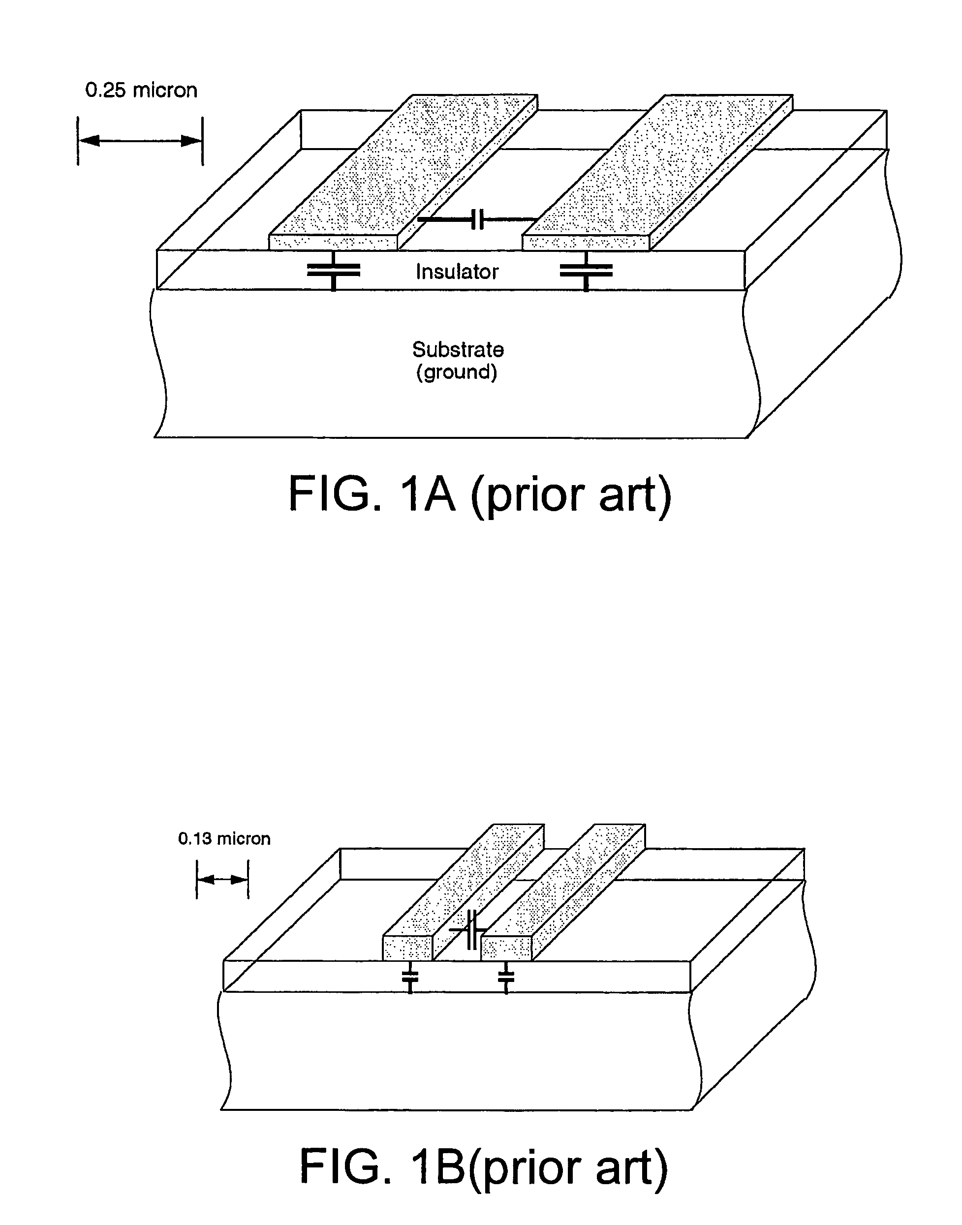
BACKGROUND[0001]1. Field of the Invention[0002]The invention relates to verification of a design of an integrated circuit (IC). More specifically, the invention relates to a method and an apparatus to overcome undesirable electrical interaction (called “capacitive crosstalk”) which may arise between wires and / or devices that are physically placed and / or routed adjacent to one another in an IC design.[0003]2. Related Art[0004]Crosstalk is an undesirable electrical interaction between two or more physically adjacent nets due to capacitive cross-coupling. As integrated circuit technologies advance toward smaller geometries, crosstalk effects become increasingly important. The reasons for crosstalk are apparent from reviewing FIGS. 1A and 1B. As circuit geometries become smaller, wire interconnections become closer together and taller, thus increasing the cross-coupling capacitance between nets. At the same time, parasitic capacitance to the substrate (see FIGS. 1A and 1B) becomes less ...

Claims


Application Information

Patent Timeline
Patent Type & Authority Patents(United States)
IPC IPC(8): G06F17/50
CPCG06F17/5022G06F17/5031G06F30/3312G06F30/33G06F30/3315
Inventor OH, NAHMSUKFALLAH-TEHRANI, PEIVANDKASNAVI, ALIREZA
Owner SYNOPSYS INC
Learn More