Particle-beam exposure apparatus and particle-beam therapeutic apparatus

a technology which is applied in the field of exposure apparatus and exposure apparatus of particle beam therapy, can solve the problems of inability to narrow the diameter of charged particle beam to the needed size, patient intimidation by movement noise, etc., and achieve spatially accurate exposure into the target, reduce the effect of diameter increas

Active Publication Date: 2008-11-11
MITSUBISHI ELECTRIC CORP
View PDF7 Cites 5 Cited by
  • Summary
  • Abstract
  • Description
  • Claims
  • Application Information

AI Technical Summary

Benefits of technology

[0008]An objective of the present invention, which is made to solve the above described problems, is to obtain a particle-beam exposure apparatus and a particle-beam therapeutic apparatus, in which, by reducing diameter increase, due to scattering in a range shifter, of a charged particle beam, the charged particle beam whose diameter is so narrow that spatially accurate exposure into the target is possible can be supplied, as well as, by placing the range shifter at a position apart from a patient, intimidation caused by a movement noise, etc. can be prevented.
[0009]A particle-beam exposure apparatus and a particle-beam therapeutic apparatus include a range shifter for varying energy of a charged particle beam with a thickness of the range shifter being changed during exposure of the charged particle beam, so that a range of the charged particle beam at a target to be exposed is set to a desired value; and a set of quadrupole magnets, being placed between the range shifter and the target, based on the magnetization amount of the set of quadrupole magnets being controlled corresponding to the charged-particle-beam energy varied by the range shifter, for reducing diameter increase, due to scattering at the range shifter, of the charged particle beam at the target.
[0010]According to this method, the beam diameter at the target can be set to a smaller value than that in the conventional method, and spatially accurate exposure into the target can be realized; moreover, the range shifter can be placed at a position apart from the target.

Problems solved by technology

Because the conventional particle-beam exposure apparatus is configured as above, the range shifter has had to be placed dose to the target; therefore, in a case of a therapeutic apparatus using the particle-beam exposure apparatus for exposing the particle beam to the head and neck portion of a patient, because of the spatial interference with the shoulder of the patient, the range shifter cannot be drawn to the portion to be exposed, and consequently, a problem has occurred in which the charged-particle-beam diameter cannot be narrowed to a needed size.
Moreover, because the range shifter whose thickness is needed to be changed during treatment has been placed dose to the patient, especially when high-speed driving of the range shifter is performed, a problem has occurred in which the patient feels intimidated by a movement noise.
Furthermore, because the beam diameter at the target is almost determined by contribution of scattering in the range shifter and the target, the beam diameter cannot be narrowed by the set of quadrupole magnets or the beam collimator placed at the upstream side of the range shifter along the beam traveling direction; consequently, in the conventional apparatus, only controlling towards the direction in which the beam diameter is widened has been possible.

Method used


Image

  • Particle-beam exposure apparatus and particle-beam therapeutic apparatus
  • Particle-beam exposure apparatus and particle-beam therapeutic apparatus
  • Particle-beam exposure apparatus and particle-beam therapeutic apparatus

Examples


embodiment 1

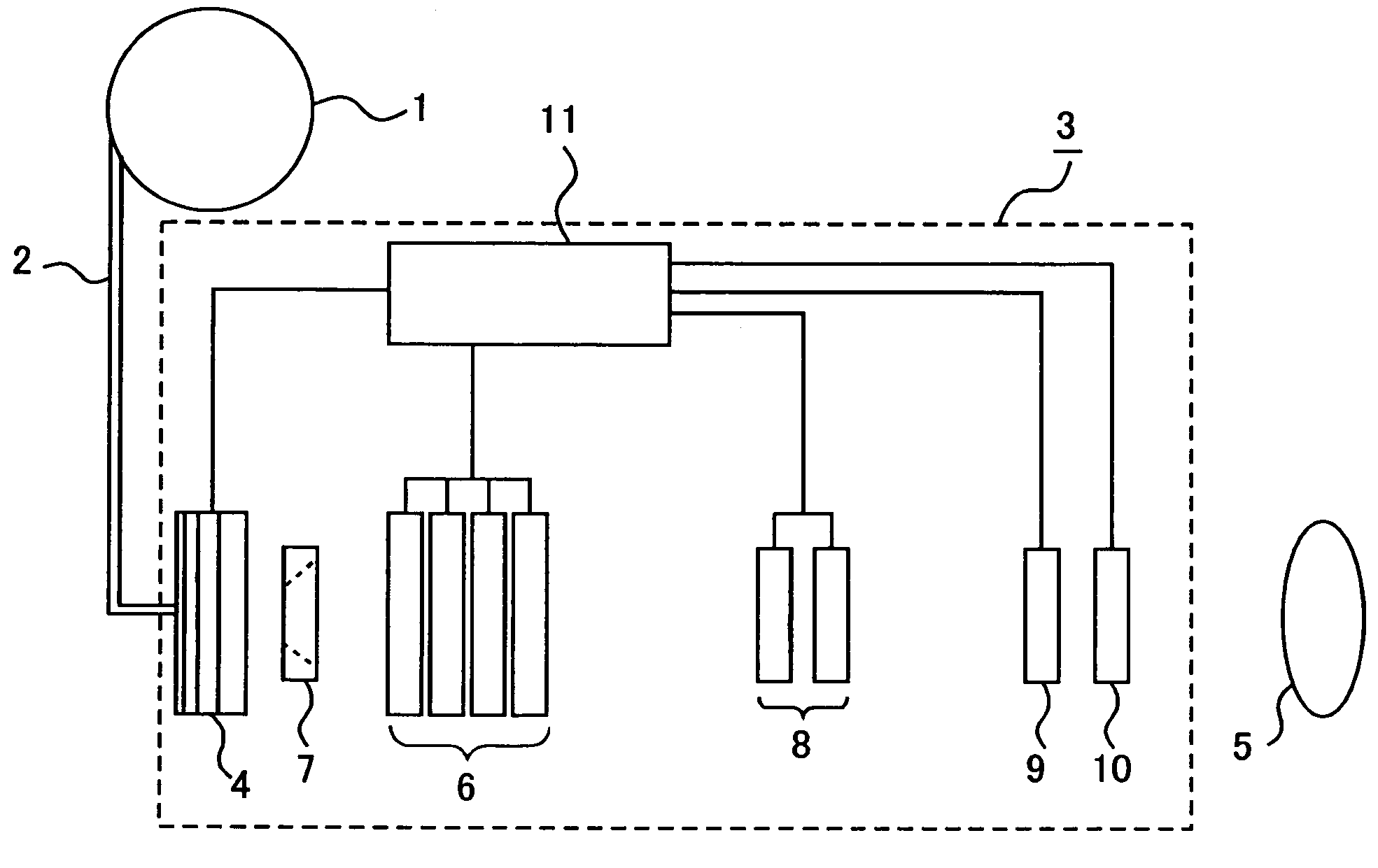
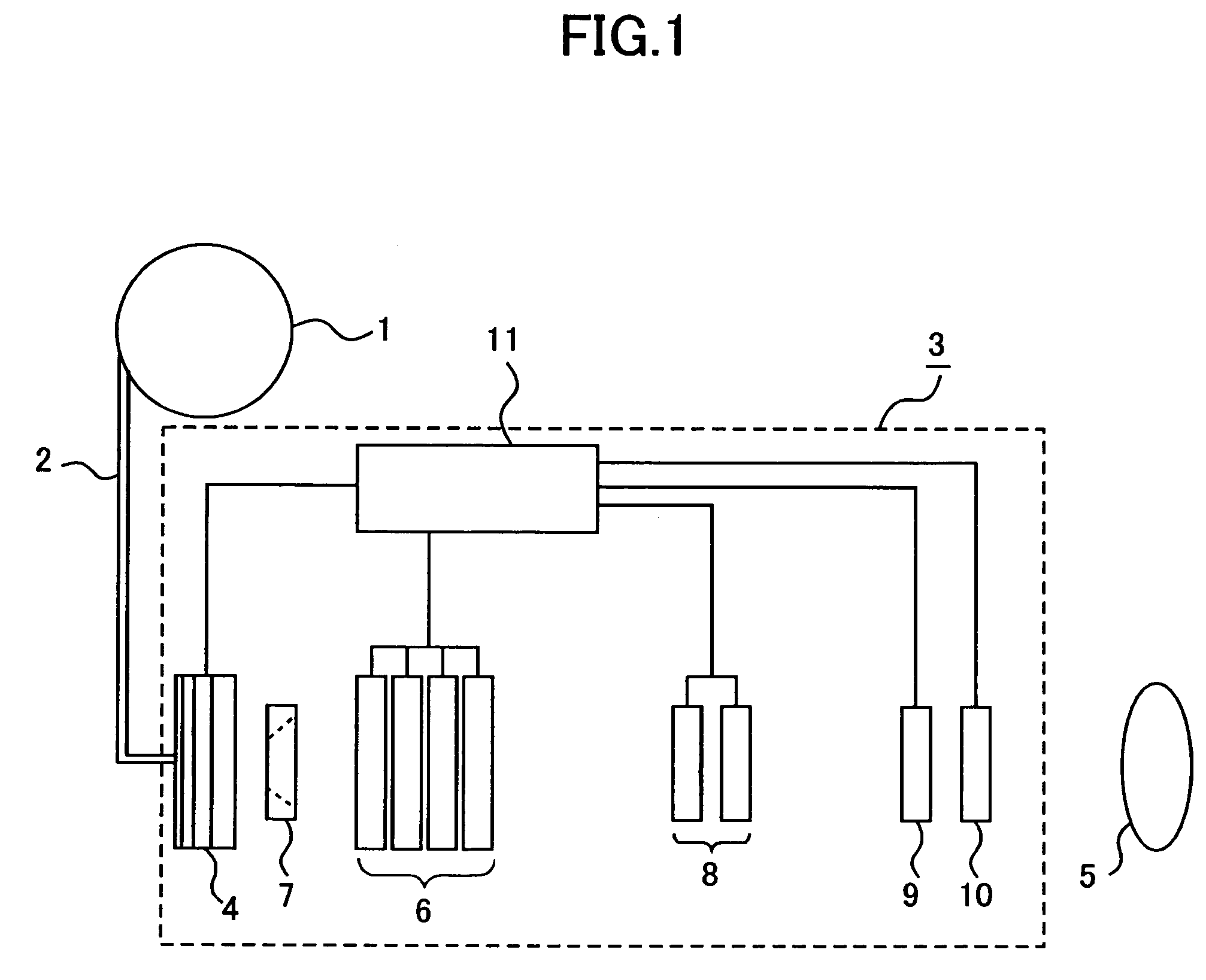
[0016]Hereinafter, a particle-beam exposure apparatus, and a particle-beam therapeutic apparatus composed of this particle-beam exposure apparatus, a particle accelerator, and a beam transport system, according to Embodiment 1 of the present invention, are explained based on FIG. 1. In FIG. 1, after a charged particle beam generated in a particle accelerator 1 is introduced into a particle-beam exposure apparatus 3 through a beam transport system 2, first, the charged particle beam passes through a variable-type range shifter 4 for decreasing, by passing through an acrylic board therein, the energy of the charged particle beam. A set of quadrupole magnets 6 for reducing diameter increase of the charged particle beam due to the variable-type range shifter 4 is placed between this variable-type range shifter 4 and a target 5 to be exposed. Moreover, a fixed-type beam slit 7, whose aperture diameter is fixed, for limiting increase of the divergence angle of the charged particle beam is...

embodiment 2

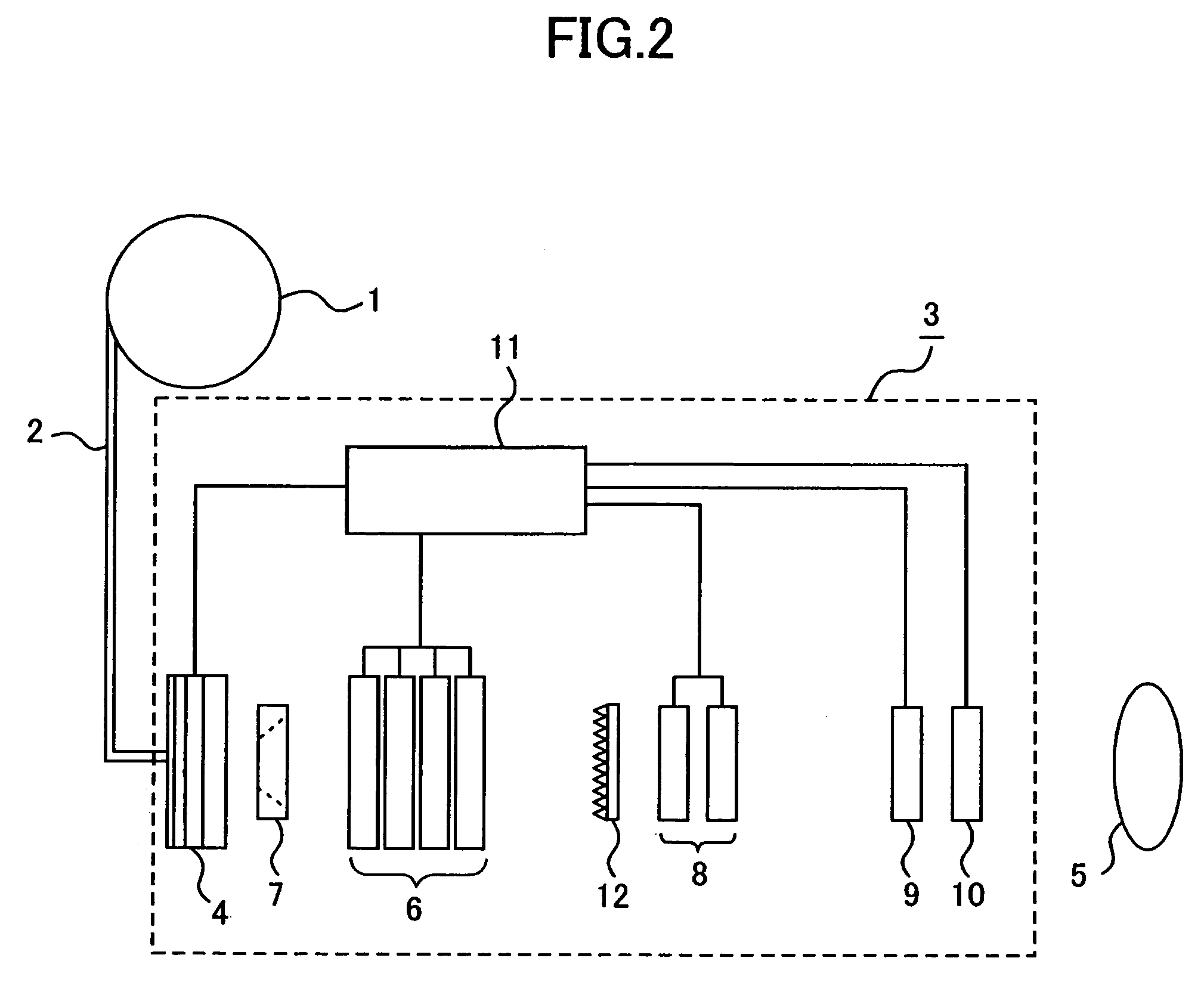
[0029]If the acrylic board is not inserted into the variable-type range shifter 4, the divergence at the variable-type range shifter 4 is prevented; however, thus, when the varying of the divergence angle at the variable-type range shifter 4 is widened, the beam-diameter control becomes complicated. In a particle-beam exposure apparatus and a particle-beam therapeutic apparatus according to Embodiment 2, as represented in FIG. 3, by providing a thin beam scatterer 13 composed of, for example, a tungsten or a lead thin film, even when the acrylic board is not inserted into the variable-type range shifter 4, the divergence angle of the charged particle beam being incident onto the set of quadrupole magnets 6 is made to be widened; thereby, the varying ratio of the divergence angle due to varying of the thickness of the acrylic board included in the variable-type range filter 4 is made to be relatively small. By providing the beam scatterer 13, it is prevented that the magnetization am...

embodiment 3

[0030]In Embodiment 1, in order to decrease the charged-particle-beam energy, the case in which only the variable-type range shifter 4 provided at the upstream side apart from the target 5 along the beam traveling direction is used has been explained; however, as represented in FIG. 4, by providing a fixed-type range shifter 14 close to the target 5, the charged-particle-beam energy being incident onto the target 5 can also be decreased at the downstream side of the set of quadrupole magnets 6 along the beam traveling direction. When the charged-particle-beam energy is decreased using the variable-type range shifter 4 into a value where the beam is stopped at the surface proximity of the target 5, because the momentum width of the charged particle beam passing through the variable-type range shifter 4 significantly increases, the beam focusability of the set of quadrupole magnets 6 decreases due to the effect of the chromatic aberration; accordingly, the charged-particle-beam diamet...


PUM


Abstract

A particle-beam exposure apparatus and a particle-beam therapeutic apparatus are obtained, in which, by reducing diameter increase, due to scattering in a range shifter, of a charged particle beam, the charged particle beam whose diameter is so narrow that spatially accurate exposure into the target is possible can be supplied, as well as, by placing the range shifter at a position apart from a patient, intimidation caused by a movement noise, etc. can be prevented. A particle-beam exposure apparatus and a particle-beam therapeutic apparatus include a range shifter 4 for varying energy of a charged particle beam with a thickness of the range shifter 4 being changed during exposure of the charged particle beam, so that a range of the charged particle beam at a target 5 to be exposed is set to a desired value; and a set of quadrupole magnets 6, being placed between the range shifter 4 and the target 5, based on the magnetization amount of the set of quadrupole magnets 6 being controlled corresponding to the charged-particle-beam energy varied by the range shifter 4, for reducing diameter increase, due to scattering at the range shifter 4, of the charged particle beam at the target 5.

Description

BACKGROUND OF THE INVENTION[0001]1. Field of the Invention[0002]The present invention relates to particle-beam exposure apparatuses exposing, into targets to be exposed, charged particle beams supplied by particle accelerators, and to particle-beam therapeutic apparatuses using the particle-beam exposure apparatuses.[0003]2. Description of the Related Art[0004]In a conventional particle-beam exposure apparatus using a range shifter for varying a range of a charged particle beam inside a target to be exposed, in order to reduce the variation, due to scattering in the range shifter, of the charged-particle-beam diameter, the range shifter has been placed close to the target, and a scatter device as beam scatterer as well as a set of quadrupole magnets has also been placed at the upstream side of the range shifter along the beam traveling direction (for example, referring to Patent Document 1), or a beam collimator has been placed (for example, referring to Patent Document 2).[0005][Pa...

Claims


Application Information

Patent Timeline
Patent Type & Authority Patents(United States)
IPC IPC(8): A61N5/10H01J33/02
CPCG21K1/10G21K5/04A61N2005/1087A61N2005/1095A61N5/1043
Inventor YOSHIDA, KATSUHISA
Owner MITSUBISHI ELECTRIC CORP
Why Eureka
Try Eureka