Piezoelectric ceramic element and portable device
a technology of ceramic elements and piezoelectric transducers, applied in piezoelectric/electrostrictive transducers, mechanical vibration separation, generators/motors, etc., to achieve the effect of easy manufacturing, high reliability in operation or movement, and thin thickness
- Summary
- Abstract
- Description
- Claims
- Application Information
AI Technical Summary
Benefits of technology
Problems solved by technology
Method used
Image
Examples
first embodiment
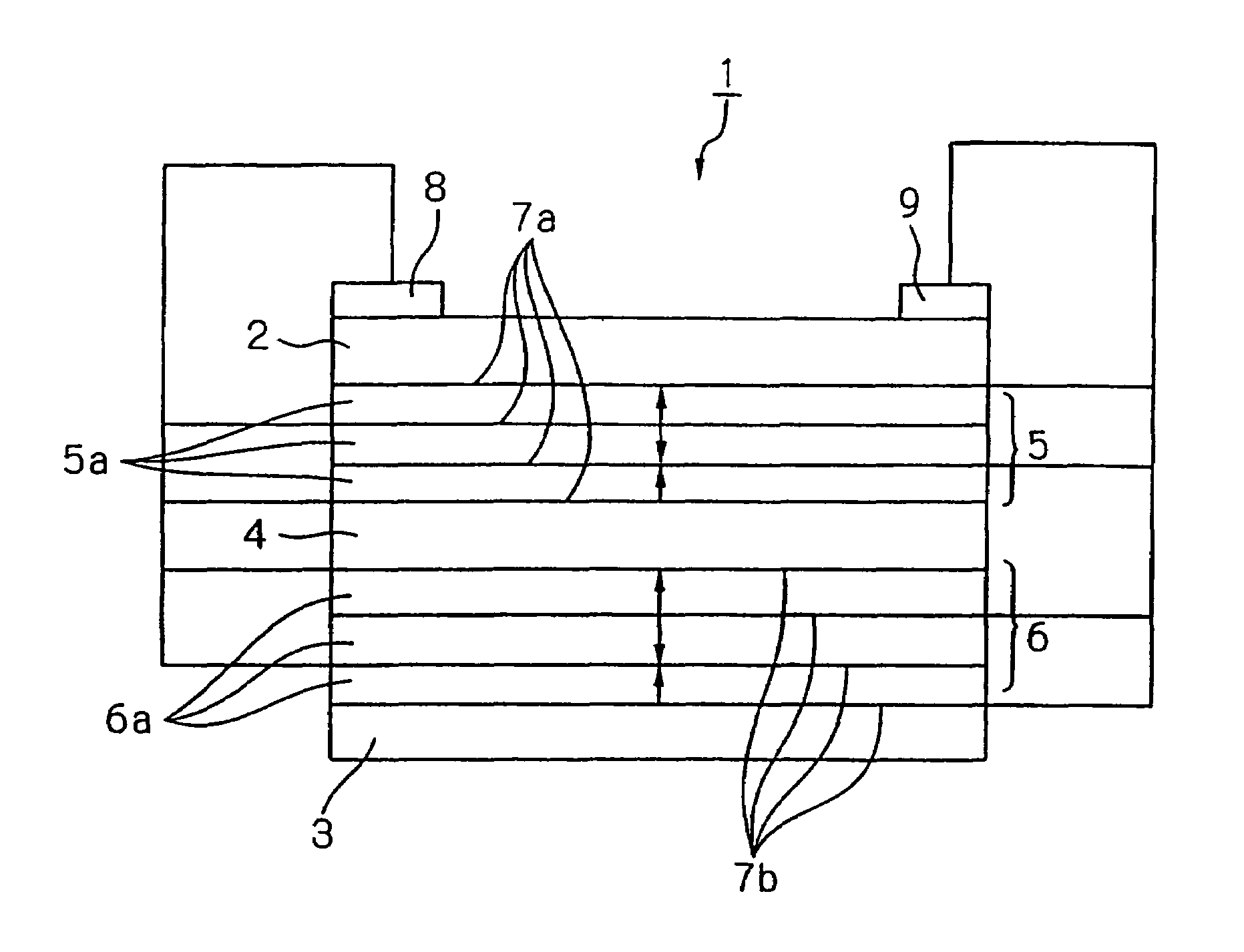
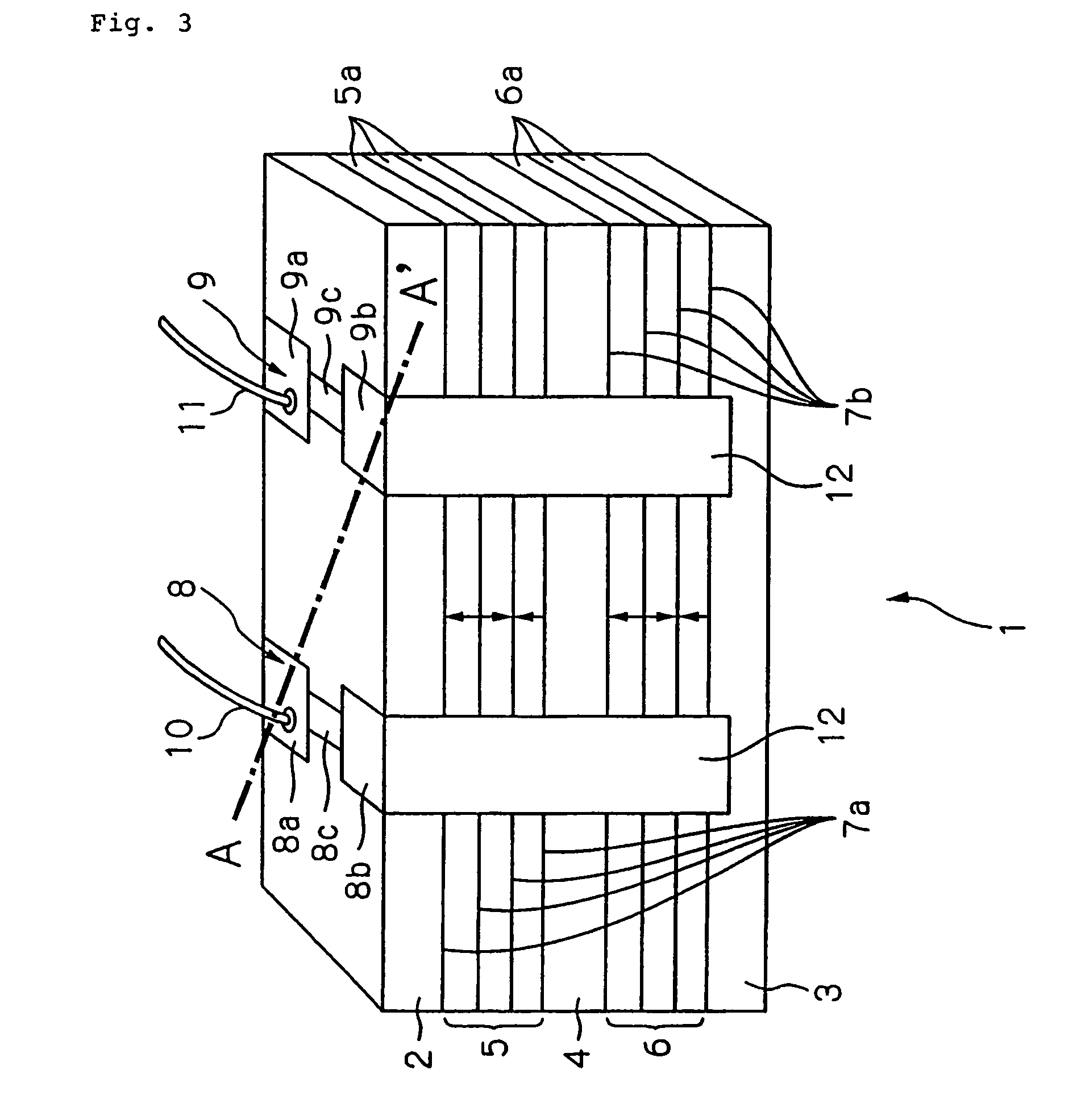
[0050]Referring to FIG. 3, a schematic view of piezo-electric ceramic transducer 1 according to a first embodiment of the present invention is shown.
[0051]Piezo-electric ceramic transducer 1 shown in FIG. 3 is a bimorph type bendable device having two piezo-electric active layers composed of upper piezo-electric active layer 5 and lower piezo-electric active layer 6 and is bent and displaced in a thickness direction of piezo-electric ceramic transducer 1 when a voltage is applied to piezo-electric ceramic transducer 1 through electrode pads 8 and 9. When the applied voltage is a direct current voltage, piezo-electric ceramic transducer 1 is displaced towards one direction. When the applied voltage is an alternating current voltage, piezo-electric ceramic transducer 1 is vibrated. The vibration is periodical repetition of bends and displacements in opposite directions. Therefore, in following descriptions, when the vibration is not particularly distinguished from the displacement, th...
second embodiment
[0083]Referring to FIG. 8, a perspective view of an acoustic device using a piezo-electric ceramic transducer according to a second embodiment of the present invention is shown.
[0084]In the present embodiment, stationary part 36 is attached to piezo-electric ceramic transducer 21, and stationary part 36 is fixed to elastic body 35. Because piezo-electric ceramic transducer 21 is the same as that described in the first embodiment, detailed description of piezo-electric ceramic transducer 21 is omitted. Stationary part 36 changes a displacement behavior of piezo-electric ceramic transducer 21, and material of stationary part 36 is not particularly restricted on condition that the material can be joined to piezo-electric ceramic transducer 21. Resin, metal, ceramics material and the like can be used as material of stationary part 36.
[0085]Material, shape and the like of elastic body 35 are selected such that a displacement of piezo-electric ceramic transducer 21 in a thickness directio...
##ventive example 1
INVENTIVE EXAMPLE 1
[0097]In Inventive Example 1, piezo-electric ceramic transducer 51 shown in FIG. 12 was manufactured. The configuration of layers of piezo-electric ceramic transducer 51 shown in FIG. 12 is shown in FIG. 13.
[0098]In this Example, fifty piezo-electric ceramic transducers 51 were manufactured. Green sheet method used for manufacturing a ceramic condenser or the like was applied to manufacturing of each piezo-electric ceramic transducer 51. Outside dimensions of piezo-electric ceramic transducer 51 were set to be 35 mm in length, 5 mm in width and 0.532 mm in thickness. Further, the configuration of layers of piezo-electric ceramic transducer 51 was set so as to have upper insulating layer 52, upper piezo-electric active layer 55 composed of a single piezo-electric layer, upper electrode layers 57a disposed on both surfaces of upper piezo-electric active layer 55 in a thickness direction thereof, intermediate insulating layer 54, lower piezo-electric active layer 56 ...
PUM
 Abstract
Description
Claims
Application Information
 - R&D
- Intellectual Property
- Life Sciences
- Materials
- Tech Scout
- Unparalleled Data Quality
- Higher Quality Content
- 60% Fewer Hallucinations
Browse by: Latest US Patents, China's latest patents, Technical Efficacy Thesaurus, Application Domain, Technology Topic, Popular Technical Reports.
© 2025 PatSnap. All rights reserved.Legal|Privacy policy|Modern Slavery Act Transparency Statement|Sitemap|About US| Contact US: help@patsnap.com


