
Lithographic printing with polarized light

a polarized light and lithographic printing technology, applied in the field of high numerical aperture and immersion lithography, can solve the problems of difficult printing in low k applications, difficult fabrication of circuit features such as contact holes or vias, and difficult printing of high-contrast images of sufficient quality that includes contacts holes like contact arrays, etc., to achieve high image quality, improve printing, and high image quality

Inactive Publication Date: 2008-11-04
ASML HLDG NV
View PDF28 Cites 50 Cited by
  • Summary
  • Abstract
  • Description
  • Claims
  • Application Information

AI Technical Summary

Benefits of technology

This approach enables high-image quality printing of contact holes at reduced pitches, including 100-nm pitch, with improved contrast and resolution, avoiding forbidden pitches and extending the limits of conventional lithography, as demonstrated by simulations and experimental results.

Problems solved by technology

Certain circuit features, such as contact holes or vias, are especially difficult to fabricate.
Printing can be difficult in low k applications.
A high-contrast image of sufficient quality that includes groups of contacts holes like contact arrays is especially hard to print.
Techniques to enhance contrast using a very high NA and off-axis illumination have been used but these techniques fail for small pitches.
This means that if the illumination is optimized for a given pitch, printing other pitches simultaneously may become impossible.

Method used


Image

  • Lithographic printing with polarized light
  • Lithographic printing with polarized light
  • Lithographic printing with polarized light

Examples


Embodiment Construction

Table of Contents

[0041]1. Overall System[0042]2. Discussion and Simulation Results

[0043]A. Introduction

[0044]B. Resolution[0045]B.1. Theoretical resolution limits[0046]B.2. Resolution capability with off-axis illumination lithography

[0047]C. Polarization[0048]C.1. Simulation Experiment[0049]C.2. Effect of Polarization on Image Quality[0050]C.3. Polarized light, Chromeless PSM, Negative photo-resist[0051]C.4. Radially polarized light, attenuating phase-shift masks or binary masks, and positive photoresists

[0052]D. Polarization With Chromeless Alternating PSM[0053]D.1. Chromeless Alternating PSM In Conjunction With Radially Polarized Light, 100-nm Pitch Nested Contacts[0054]D.2. Through-Pitch Behavior, Chromeless Contacts With Radially Polarized Light[0055]D.3. Custom Polarization

[0056]E. Immersion Lithography

[0057]F. EUV

[0058]While specific configurations and arrangements are discussed, it should be understood that this is done for illustrative purposes only. A person skilled in the ...


PUM

PropertyMeasurementUnit
wavelengthaaaaaaaaaa
contrastaaaaaaaaaa

Abstract

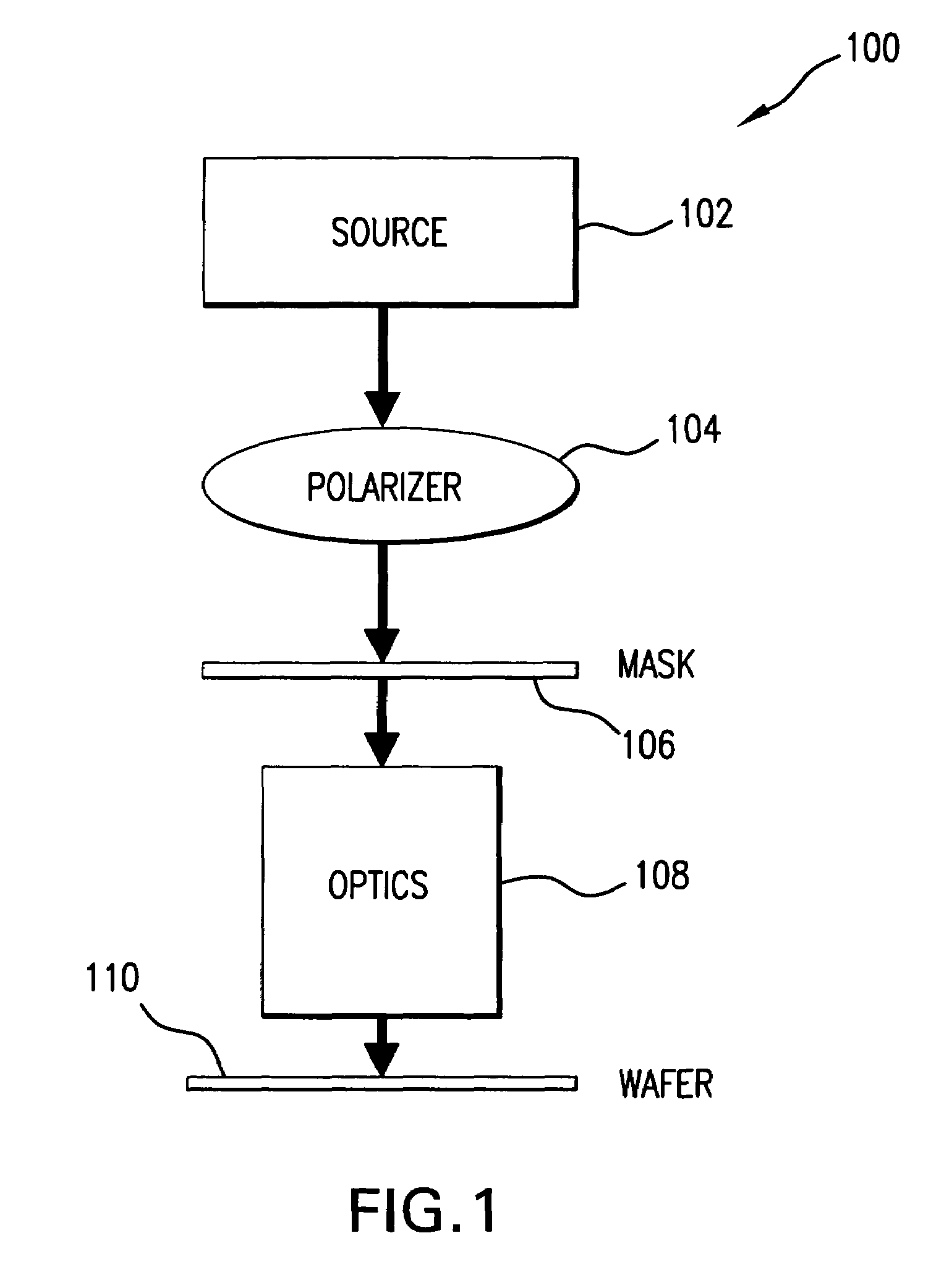
The present invention provides systems and methods for improved lithographic printing with polarized light. In embodiments of the present invention, polarized light (radially or tangentially polarized) is used to illuminate a phase-shift mask (PSM) and produce an exposure beam. A negative photoresist layer is then exposed by light in the exposure beam. A chromeless PSM can be used. In further embodiments of the present invention, radially polarized light is used to illuminate a mask and produce an exposure beam. A positive photoresist layer is then exposed by light in the exposure beam. The mask can be an attenuating PSM or binary mask. A very high image quality is obtained even when printing contact holes at various pitches in low k applications.

Description

CLAIM TO PRIORITY[0001]This application is a continuation of U.S. Non-provisional Appl. Ser. No. 10 / 781,803, filed, Feb. 20, 2004, of like title, which claims priority to U.S. Provisional Appl. No. 60 / 448,530, filed Feb. 21, 2003. Both are incorporated herein by reference in their entirety.BACKGROUND OF THE INVENTION[0002]1. Field of the Invention[0003]The present invention relates to high numerical aperture and immersion lithography.[0004]2. Related Art[0005]Lithographic tools and techniques are increasingly called upon to print patterns at a high resolution. For example, in the manufacture of semiconductor dies or chips, patterns of circuit features, such as lines, contact holes, or other elements, often need to be printed at a high resolution to improve the packing density of circuit elements and reduce the pitch of the pattern. Certain circuit features, such as contact holes or vias, are especially difficult to fabricate.[0006]A well-known parameter relating to lithography resol...

Claims


Application Information

Patent Timeline
Patent Type & Authority Patents(United States)
IPC IPC(8): G02B5/30G03B27/72G03B27/54G03C5/00G03FG03F7/20G03F9/00
CPCG03F7/2006G03F7/70566G02B27/28G03F7/2041
Inventor BABA-ALI, NABILAKREUZER, JUSTINSEWELL, HARRY
Owner ASML HLDG NV
Learn More