Control of pressurized microchannel processes

a microchannel and process technology, applied in process and machine control, combustible gas production, chemical production, etc., can solve the problems of increasing the risk of damage to the device, increasing the complexity of the device, and reducing so as to increase the concentration of low-thermal energy density materials. , the effect of decreasing the proportion of diluen

Inactive Publication Date: 2008-11-04
VELOCYS INC
View PDF25 Cites 8 Cited by
  • Summary
  • Abstract
  • Description
  • Claims
  • Application Information

AI Technical Summary

Benefits of technology

[0054]Importantly, presence of the containment vessel 20 operating as a thermal blanket over, for example, the second process unit 40, enables improved thermal control. Where the second process unit 40 comprises a catalyzed combustion unit operation, the catalyst may be required to function at a designed temperature of 700-900 deg. C. but may be required to be active at a much lower temperature for startup. Thus, the ability to raise the temperature of the second process unit 40 from ambient to, for example, 300 deg. C., enables greater catalyst design flexibility. Filling the containment vessel 20 with, for example, superheated steam, can achieve such temperatures. Additionally, during normal operation the pressurizing material D contained within the containment vessel 20 may function to reduce heat loss from the first process unit 30 and the optional second process unit 40 to ambient could be reduced, thus reducing any temperature gradient within the process units 30, 40 resulting in potentially improved overall performance. For example, with an exemplary endothermic reaction such as SMR, lower temperatures in peripheral microchannels could cause lower conversion in those channels.

Problems solved by technology

Unlike a tubular reactor, a multi-planar device does not easily handle such pressures at the temperatures required.
In addition to the structural integrity issues raised by planar elements and laminations and the temperature and pressure issues noted above, thin walls to reduce weight and improve heat transfer add further complexity.
This is even more evident during startup and shutdown (both normal and emergency and including shutdown and subsequent “hot startup”) when temperature and pressure dynamics can be most difficult to control and which have the potential to damage the device or create hazardous conditions when flammable or potentially explosive mixtures are present.

Method used


Image

  • Control of pressurized microchannel processes
  • Control of pressurized microchannel processes
  • Control of pressurized microchannel processes

Examples


Embodiment Construction

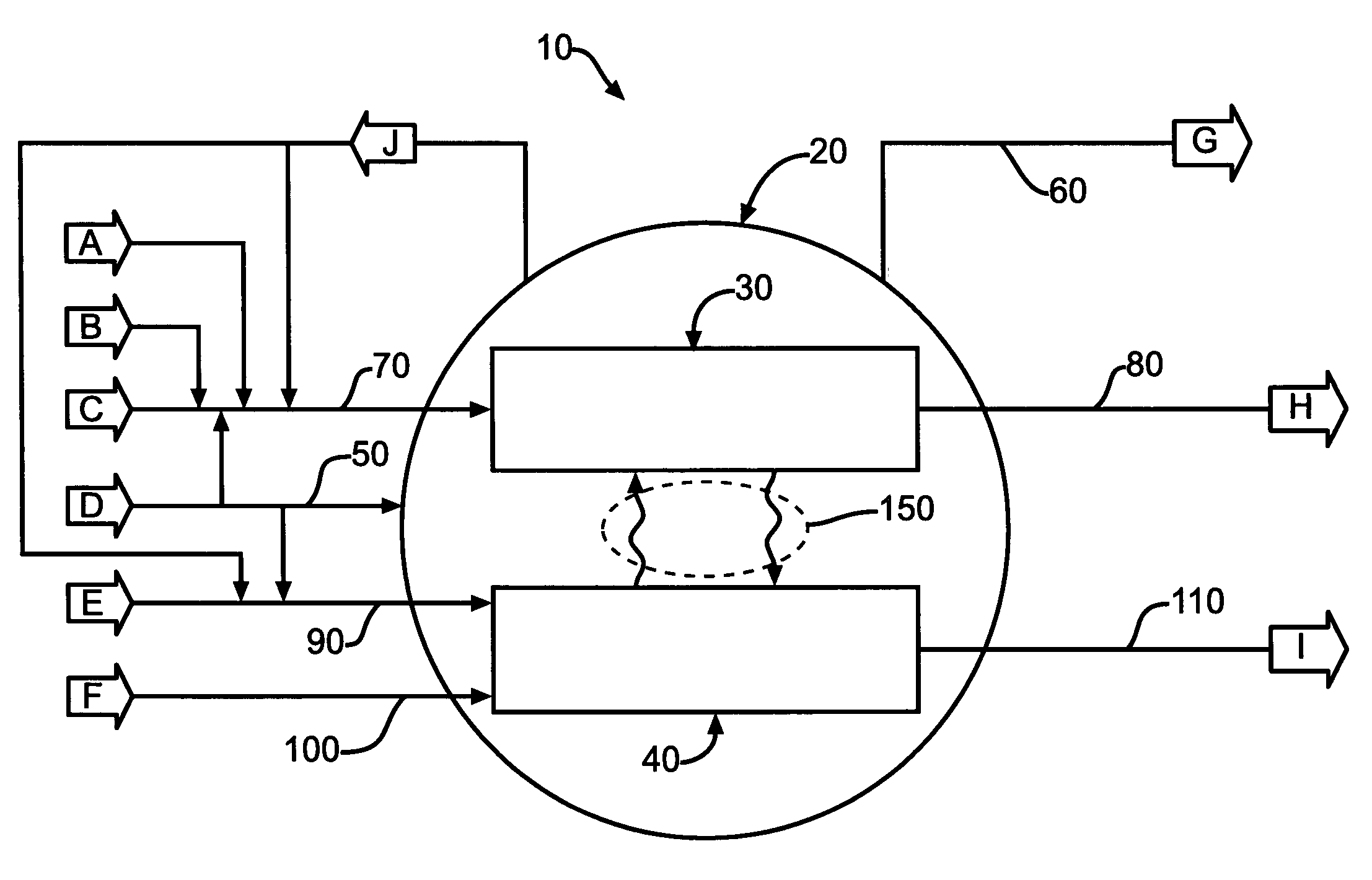
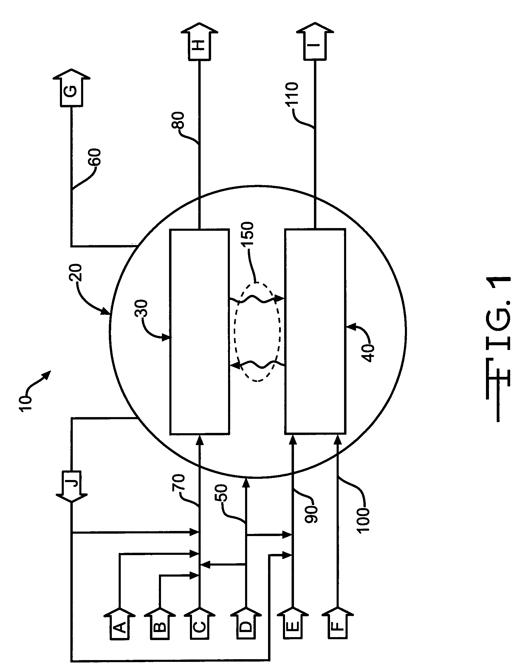
[0020]The following reference indicators are provided as an aid to an understanding of the figures:[0021]10 microchannel process[0022]20 containment vessel[0023]30 first microchannel process unit[0024]40 second microchannel process unit[0025]50 containment vessel inlet[0026]60 containment vessel vent[0027]70 first microchannel process unit inlet[0028]80 first microchannel process unit outlet[0029]90 first process unit inlet to second microchannel process unit[0030]100 second process unit inlet to second microchannel process unit[0031]110 second microchannel process unit outlet[0032]150 process unit—process unit heat transfer[0033]A first reactant material[0034]B first catalyst activation material[0035]C second reactant material[0036]D pressurizing material[0037]E third reactant material[0038]F fourth reactant material[0039]G vented / flared material[0040]H first products material[0041]I second products material[0042]J purge material

[0043]Reference to FIG. 1, an exemplary microchannel ...


PUM

PropertyMeasurementUnit
heightaaaaaaaaaa
heightaaaaaaaaaa
pressureaaaaaaaaaa

Abstract

A method of starting up and shutting down a microchannel process is provided. Included are the steps of providing a first multi-planar process unit, preferably adapted to process an endothermic reaction, a second multi-planar process unit, preferably adapted to process an exothermic reaction, providing a containment vessel, the containment vessel containing at least a portion of the first, and preferably the second, process unit. In startup, the microchannel process is first checked for pressure integrity by pressurizing and checking the important components of the process for leaks. Subsequently, the process units are heated by introducing a dilute low-thermal energy density material, preferably to the second process unit, followed by the introduction of a dilute high-thermal energy density material, and adjusting the proportion of high-thermal energy density material as required. In shutdown, a purge material from the containment vessel is introduced into the first, and preferably the second, process unit.

Description

CROSS-REFERENCE TO RELATED APPLICATION[0001]This application claims priority to, and is a Continuation-in-Part of, application Ser. No. 10 / 774,298, filed Feb. 6, 2004, the contents of which, to the extent not inconsistent herewith, are incorporated herein by reference as if fully rewritten herein.STATEMMENT REGARDING FEDERALLY-SPONSORED RESEARCH OR DEVELOPMENT[0002]Not Applicable.INCORPORATION-BY-REFERENCE OF MATERIAL SUBMITTED ON A COMPACT DISC[0003]Not Applicable.BACKGROUND OF THE INVENTION[0004]1. Field of the Invention[0005]The present invention is related to the control of microchannel processes, particularly microchannel processes which operate under generally high pressures and, optionally, generally high temperatures, and, more particularly, microchannel processes which comprise endothermic reactions such as steam methane reforming (SMR), and, optionally, exothermic reactions such as combustion. Control includes, particularly, methods of startup and shutdown of such processe...

Claims


Application Information

Patent Timeline
Patent Type & Authority Patents(United States)
IPC IPC(8): C01B3/24B01L3/00C01B3/02C01B3/36F01N3/20B01J3/00B01J8/02B01J8/04B01J10/00B01J19/00B01J19/24C01B3/38C07C27/00
CPCB01J19/0093C01B3/384B01J3/046C07C1/0485C01B3/382C07C1/0475Y10T29/49948B01J2219/00835B01J2219/00867B01J2219/00869B01J2219/00873B01J2219/00891B01J2219/00963B01J2219/00986C01B2203/0227C01B2203/0283C01B2203/0811C01B2203/1604B01J2219/00817B01J2219/00957B01J2219/00961Y10T29/49826Y10T29/49815Y10T29/49345B01J2219/0081C10G2/00C10G2300/4031Y02P20/52Y10T137/0335
Inventor WEIL, CHRISTOPHER P.LITT, ROBERT D.ROGERS, JR., WILLIAM ALLENBENNETT, RICHARD K.DE LUCIA, ELIZABETH A.
Owner VELOCYS INC
Why Eureka
Try Eureka