
Method for transporting a piping structure

a piping structure and transport method technology, applied in the field of hanging brackets, can solve the problems of time-consuming and expensive tracking of leakage, cumbersome installation,

Inactive Publication Date: 2008-11-04
KARAMANOS JOHN
View PDF52 Cites 21 Cited by
  • Summary
  • Abstract
  • Description
  • Claims
  • Application Information

AI Technical Summary

Benefits of technology

[0008]One advantage of the invention is that the assembled base and pipe may be classified as a capital piece of equipment and depreciated accordingly. In the prior art, the structure could not be treated as such because the bulk of the cost is in assembly, whereas in the invention the assembly cost is built in to the cost of the product.
is that the assembled base and pipe may be classified as a capital piece of equipment and depreciated accordingly. In the prior art, the structure could not be treated as such because the bulk of the cost is in assembly, whereas in the invention the assembly cost is built in to the cost of the product.

Problems solved by technology

Builders, or contractors, typically use ladders or scaffolding to reach areas where piping is routed and the installation may be cumbersome.
After installation, a pressure check of the piping and conduit system often reveals leaks that are time-consuming and expensive to track down.

Method used


Image

  • Method for transporting a piping structure
  • Method for transporting a piping structure
  • Method for transporting a piping structure

Examples


Embodiment Construction

[0015]The following description of the invention is not intended to limit the scope of the invention to these embodiments, but rather to enable any person skilled in the art to make and use the invention.

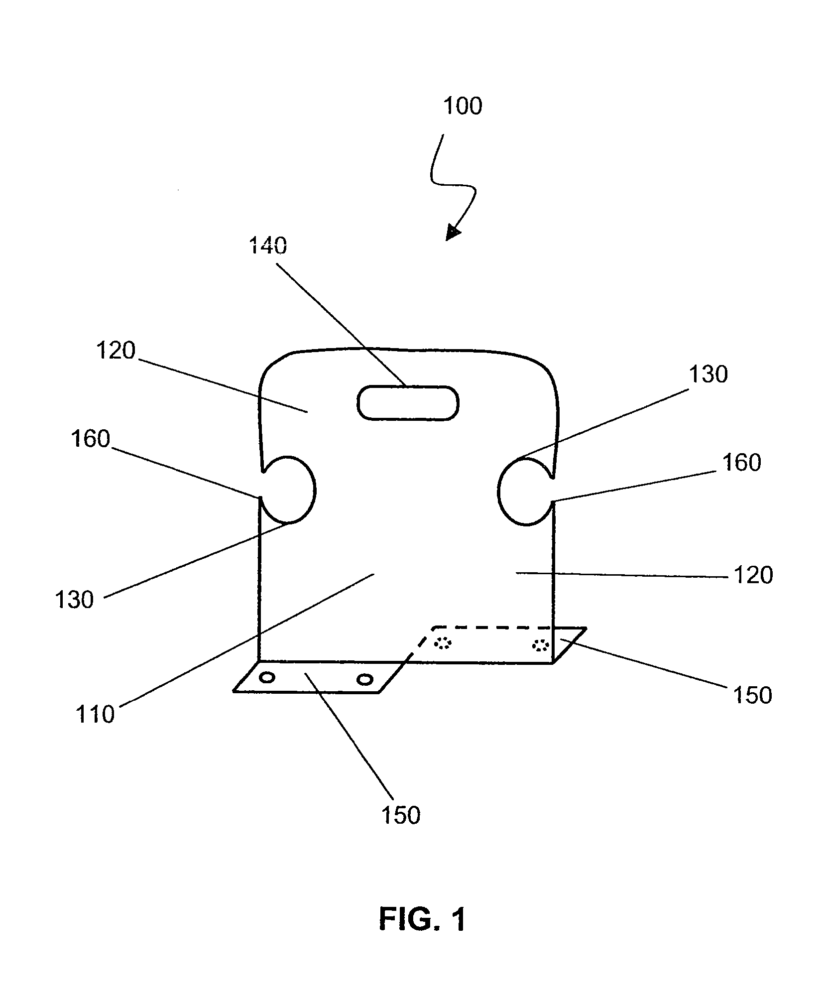
[0016]FIG. 1 is a diagram illustrating a bracket for mounting and transporting pipe or conduit with a built-in handle. Bracket 100 includes body 110, arms 120 with support guides 130. Support guides 130 may secure pipes or conduits, and may include a grommet (not shown) to assist in securing the pipe. A pipe may be inserted into support guides 130 through either support guide opening 160, on the side of support guide 130, or directly through the larger opening of support guide 130. A retaining clip or U-clip, may be used to secure a pipe within support guide 130. The support guides support pipes by providing, either in combination with a grommet or without a grommet, friction along the pipe and maintaining alignment of the pipe at approximately 90 degrees to the plane of the bracket...


PUM

PropertyMeasurementUnit
pressure/temperatureaaaaaaaaaa
pressureaaaaaaaaaa
frictionaaaaaaaaaa

Abstract

The invention is a method of transporting a pipe mounted within a plurality of brackets, each bracket having a body, an arm coupled to the body, a support guide located within the arm and configured to provide support to the pipe, a base coupled to the body and configured to attach a platform, the base further configured to provide support to the body, a spacer coupled to the body and configured to maneuver the bracket, wherein each bracket is configured to maintain support for the pipe while the bracket is maneuvered by the spacer. The method comprises the following. Position the plurality of brackets with the spacer proximate to the transporting surface. Set the spacer of each of the plurality of brackets on the transporting surface.

Description

CROSS-REFERENCES TO RELATED APPLICATIONS[0001]This application is a continuation application of U.S. patent application Ser. No. 10 / 857,211, filed May 28, 2004, which is a continuation-in-part of U.S. patent application Ser. No. 10 / 667,117, filed Sep. 17, 2003 (U.S. Pat. No. 6,951,324), the entire disclosures of which are incorporated herein by reference for all purposes.FIELD OF INVENTION[0002]The invention relates generally to the field of hanger brackets and specifically to the shipping of heating, ventilation and air-conditioning (HVAC) piping structures.BACKGROUND OF THE INVENTION[0003]Heating, cooling, ventilating and air-conditioning systems (HVAC systems) in residential, commercial, education and research buildings are usually comprised of metallic pipes, hollow composite materials such as tubes, and the like. The systems are typically supported from and between floor or ceiling joists. The HVAC system typically includes a primary or main duct. A series of smaller branch or ...

Claims


Application Information

Patent Timeline
Patent Type & Authority Patents(United States)
IPC IPC(8): B23Q3/00A45F5/00F16L3/223F24F
CPCF16L3/223Y10T29/49901
Inventor KARAMANOS, JOHN C.
Owner KARAMANOS JOHN
Learn More