
Virtual wireless transmitter

a wireless transmitter and wireless technology, applied in the field of virtual wireless transmitters, can solve the problems of increasing the amount of circuitry in the field device, increasing the cost, and so as to achieve the effect of increasing the power consumption of the field device, increasing the amount of circuitry, and limiting the implementation of wireless systems

Inactive Publication Date: 2008-10-21
ROSEMOUNT INC
View PDF20 Cites 33 Cited by
  • Summary
  • Abstract
  • Description
  • Claims
  • Application Information

AI Technical Summary

Benefits of technology

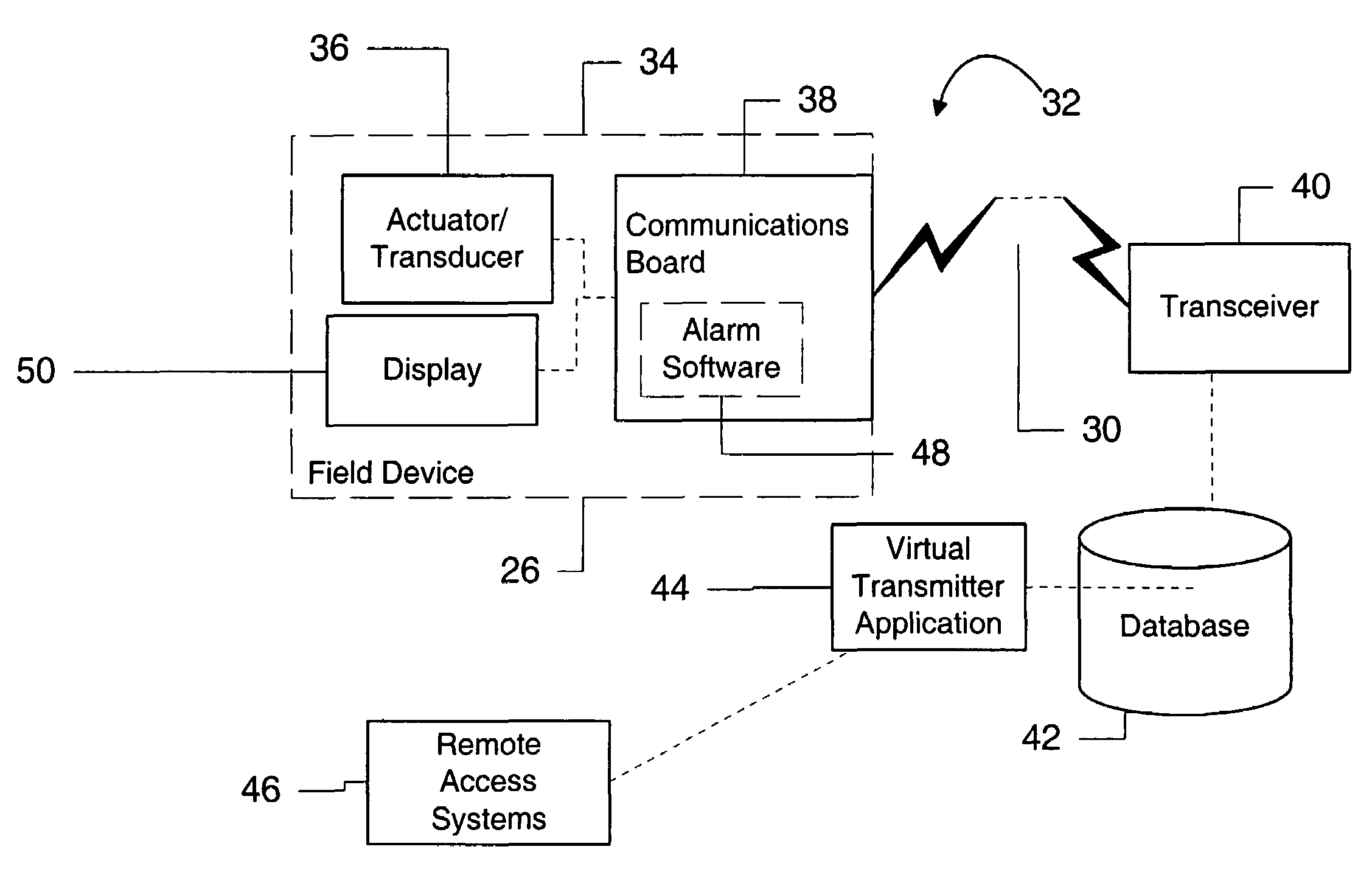
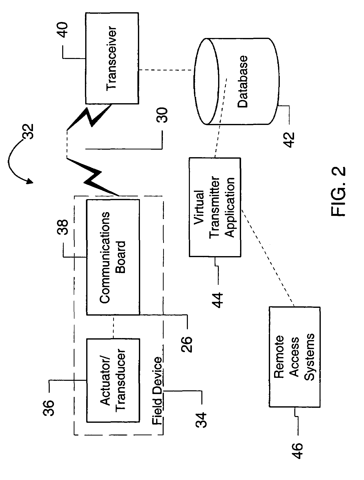
[0048]The present invention provides a number of advantages over the prior art. First, in the preferred embodiment, since no analog conversions are performed on the data, the overall accuracy of the data is increased. Second, since the virtual transmitter application 44 is a software application on the server, a software upgrade can be effected system-wide and instantaneously with one software installation, rather than adding or upgrading software in each distributed device, which would be costly, time-consuming, and often very difficult. Additionally, new functionality such as pattern recognition and new diagnostic software can be added at any time, without changing field devices, simply by adding the new application to the server. Since the data is stored in raw form, any upgrade to the virtual transmitter application is backward compatible with data in the database. The resulting monitoring system requires less circuitry, consumes less power, and is more flexible and adaptable than prior art systems that groom the data prior to transmission and storage.

Problems solved by technology

However, implementation of wireless systems has been limited due to limited coverage area, high power consumption, and cost considerations.
The introduction of the wireless communications board not only increases the amount of circuitry in the field devices, and therefore the cost, but the additional circuitry increases the power consumption of the field device.
While the wireless solution is desirable, power consumption is still too high, and the additional cost of adding a wireless transceiver to each monitoring point is still too high.

Method used


Image

  • Virtual wireless transmitter
  • Virtual wireless transmitter
  • Virtual wireless transmitter

Examples


Embodiment Construction

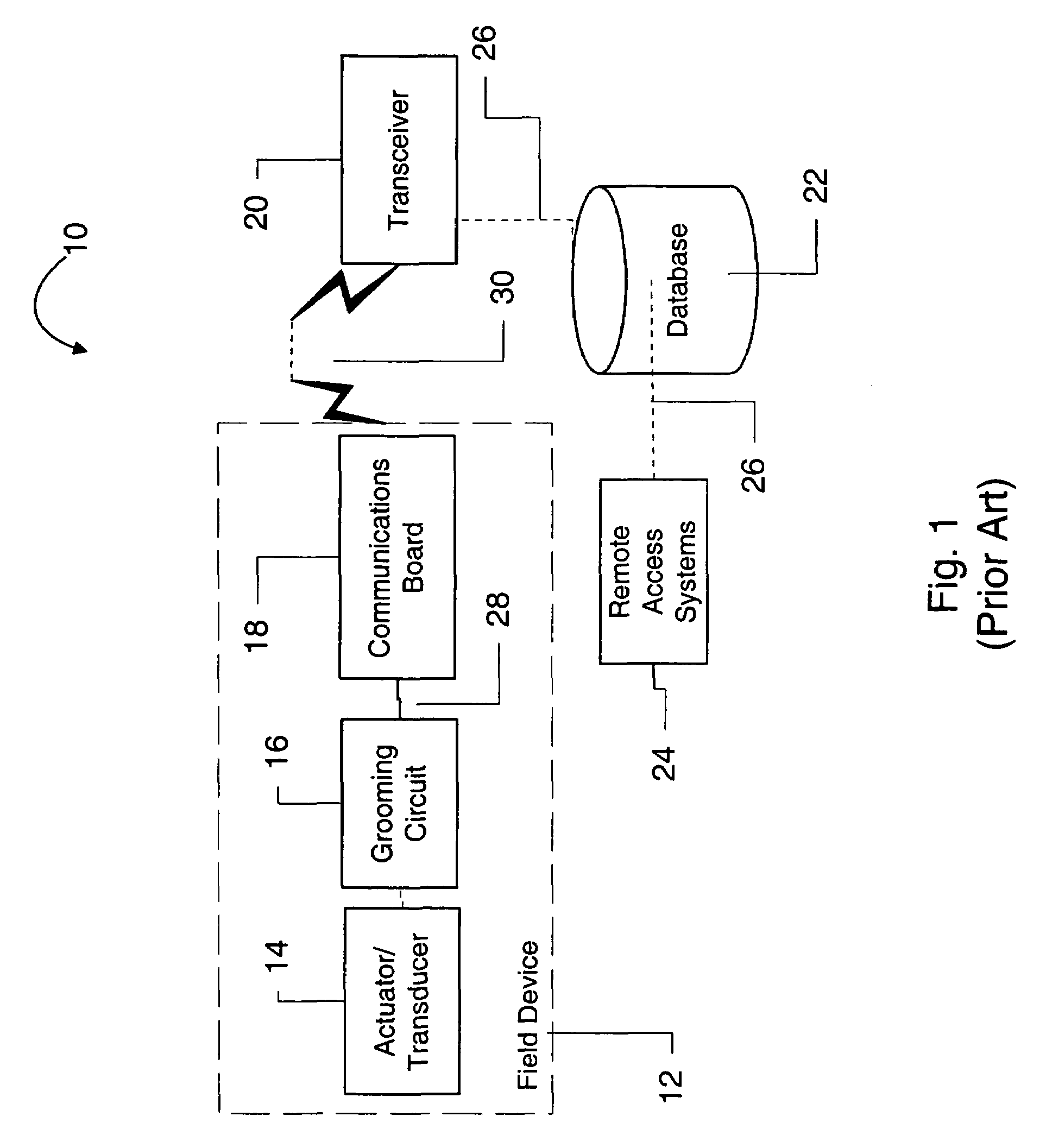
[0017]FIG. 1 shows a prior art wireless monitoring system 10. The system 10 has a field device 12, which includes a transducer 14, a grooming circuit 16, and a wireless communications board 18. In addition to the field device 12, the system 10 includes a wireless receiver 20, a short or long term data storage or a database 22, and a remote access systems 24.

[0018]For the purpose of this disclosure, the term “field device” refers to any device that performs a function in a distributed control system and is known in the control art. Each field device includes a transducer. As previously mentioned, a transducer is understood to mean either a device that generates an output signal based on a physical input or that generates a physical output based on an input signal. Types of transducers include various analytical equipment, pressure sensors, thermistors, thermocouples, strain gauges, flow transmitters, positioners, actuators, solenoids, indicator lights, and the like. As previously men...


PUM


Abstract

A distributed control system has a plurality of distributed field devices, each of which contains a transducer and a wireless transceiver. The distributed control system includes a base station transceiver, a database and a virtual transmitter application in communication with the database. Each field device transmits and receives data via wireless signals between the communications boards and the base station. The data is stored in the database for later retrieval and evaluation by the virtual transmitter application. The deployed field device senses information and transmits the sensed information wirelessly to a base station. The sensed information is stored in memory on a computer system, and programmatically groomed to provide a measurement value, upon request by a user.

Description

CROSS-REFERENCE TO RELATED APPLICATION(S)[0001]None.FIELD OF THE INVENTION[0002]The present invention relates to accessing and monitoring field devices in a distributed control system. Specifically, the invention relates to a system for retrieving raw sensor data using wireless transceivers, storing the sensor data, and grooming and evaluating the sensor data using software.BACKGROUND OF THE INVENTION[0003]In many industrial settings, control systems are used to monitor and control inventories, processes, and the like. Often, such control systems have a centralized control room, with computer systems having user inputs and outputs and having peripheral systems that are known in the art, such as printers, scanners, and the like. Generally, a controller and process subsystems are coupled to the computer systems.[0004]Typically, control systems are distributed such that field devices are separated or geographically removed from the control room. The process subsystem is connected to th...

Claims


Application Information

Patent Timeline
IPC IPC(8): H03C1/62G05B19/042
CPCG05B19/0421G05B2219/25187G05B2219/25192G05B2219/25428G05B2219/2612
Inventor KARSCHNIA, ROBERT J.PELUSO, MARCOS
Owner ROSEMOUNT INC
Learn More