Contraband detection systems and methods

a detection system and contraband technology, applied in the field of baggage inspection systems, can solve the problems of long delay in passing through security checkpoints, difficult for even the most highly trained screener to detect explosives using projection x-ray technology, and achieve the effect of automatically eliminating or excluding potential threats from objects under inspection

Active Publication Date: 2008-10-21
REVEAL IMAGING TECH
View PDF21 Cites 31 Cited by
  • Summary
  • Abstract
  • Description
  • Claims
  • Application Information

AI Technical Summary

Benefits of technology

[0014]In one embodiment, the present invention provides a CT scanner system for use in baggage screening at security checkpoints. According to one aspect of the invention, the CT scanner system processes x-ray data to locate and eliminate non-contraband without full CT reconstruction of the entire bag. For example, one embodiment of the CT scanner system disqualifies objects of insufficient size, density, or mass as potential threats. According to another aspect of the invention, the CT scanner system performs CT reconstruction of non-eliminated objects to determine whether any of the non-eliminated objects qualify as a potential threat. According to another aspect of the invention, the CT scanner system processes the data to locate weapons or explosives without operator review. According to another embodiment, a stationery x-ray projection image, whether generated from the CT scanner X-ray source in a parked position, or by a separate fixed view x-ray scanner in front of or after the CT scanner, can be used to automatically eliminate or exclude potential threats from objects under inspection.
[0017]In another embodiment, the present invention provides a high throughput, high security checkpoint screening system. An adaptive system that inspects passenger baggage based on security intelligence inputs, such as CAPPS, can provide high throughput with improved security. Compared to today's carry-on inspection process, a carry-on EDS according to the present invention can improve security and double passenger throughput, with reduced screener labor.
[0018]Deployment of EDS at checkpoints can improve the overall detection performance of the passenger screening process, and eliminate the need for redundant hand searching of selectee bags.
[0020]According to one embodiment of a method according to the invention, all non-selectee passenger bags are inspected using a standard projection image, similar to today's carry-on screening process. For a normal passenger, the CT gantry is stopped and a projection image of a bag is created. In order to support the high resolution imaging used by a CT scanner during EDS scans, the imaging electronics acquire data significantly faster than today's conventional checkpoint scanners. This increased data acquisition speed allows this embodiment of the invention to speed up the conveyor belt, without sacrificing image quality. Therefore the inspection throughput for normal passenger bags can be more than three times the throughput of a conventional carry-on X-ray system.
[0021]In one embodiment, for CAPPS selectee passengers, the “greeter” helping passengers divest before they place bags on the belt simply indicates to the system (e.g., via a button) that a selectee passenger bag is approaching the system. In a specified period of time, e.g., less than 5 seconds, the CT gantry automatically starts spinning and the EDS system inspects the selectee bag using fully automated EDS techniques. Once the selectee bag is scanned and analyzed, a process that takes a specified time, e.g., approximately 20 seconds, the gantry stops again for normal bag inspection. This entire process can be completely transparent to the passenger. The process described here can eliminate the need for separate screeners for selectee bag hand search.
[0027]Still another embodiment provides a scanner system that utilizes a visible light camera to image each bag as it crosses a predetermined point outside or inside the scanner tunnel. The image can then be used by the scanner CPU to automatically identify features of the bag and / or to alter the scan speed to optimize throughput and detection. In another embodiment, the image can be used to associate passenger bags with scanner data and with automated decisions. In another embodiment, the visible light image can be used to help a screener identify the location of a suspect object in a passenger's bags.

Problems solved by technology

In current conditions of heightened security, passengers can experience long delays in passing through security checkpoints.
Despite such imaging, the individuals using conventional projection x-ray systems to perform screening in certain circumstances do not detect forbidden objects.
Specifically, projection x-ray scanners are not designed to detect explosives.
Therefore, it is difficult for even the most highly trained screener to detect explosives using projection x-ray technology.
Conventional CT scanners do not provide a high-resolution dual energy projection x-ray image useful for detecting weapons.
Conventional CT scanning and reconstruction used in baggage inspection is slow and cumbersome.
Both of these processes result in slow movement of baggage through the scanner.
Simply replacing the existing checkpoint X-ray systems with EDS will be an expensive proposition.
Adding special selectee lanes to existing passenger checkpoints would help with throughput but limits the ability of TSA or an airport to respond to changes in the threat condition or an increase in the percentage of CAPPS selectees.
This alert can cause additional problems for TSA based on perceived discriminatory practices.
TSA and airports are struggling to keep up with passenger loads using today's passenger screening systems and procedures.
Lines up to 2 hours can form during peak periods and will likely get worse as TSA headcount is further rationalized and passenger loads increase.
Adding additional screening lanes can cost millions and take months.

Method used


Image

  • Contraband detection systems and methods
  • Contraband detection systems and methods
  • Contraband detection systems and methods

Examples


Embodiment Construction

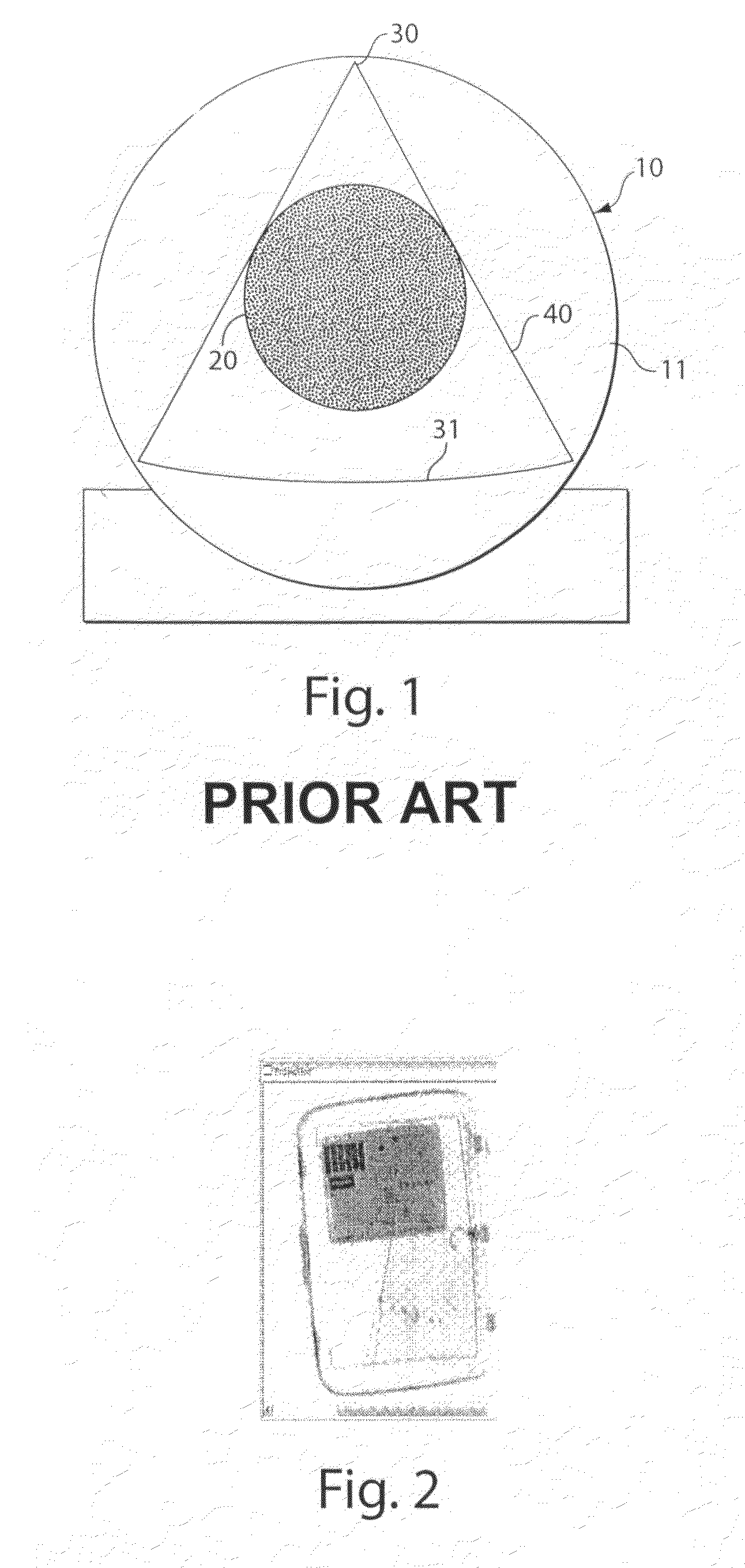
[0052]The present invention relates to baggage inspection systems. FIG. 2 illustrates an image of a bag from a projection x-ray system such as a conventional system used at security checkpoints in airports. The objects in the bag overlap each other in the image. A highly trained operator must review each image to determine whether the bag includes contraband, such as weapons, explosives, or other excluded items. If the objects cannot be clearly viewed, the bag must be hand searched.

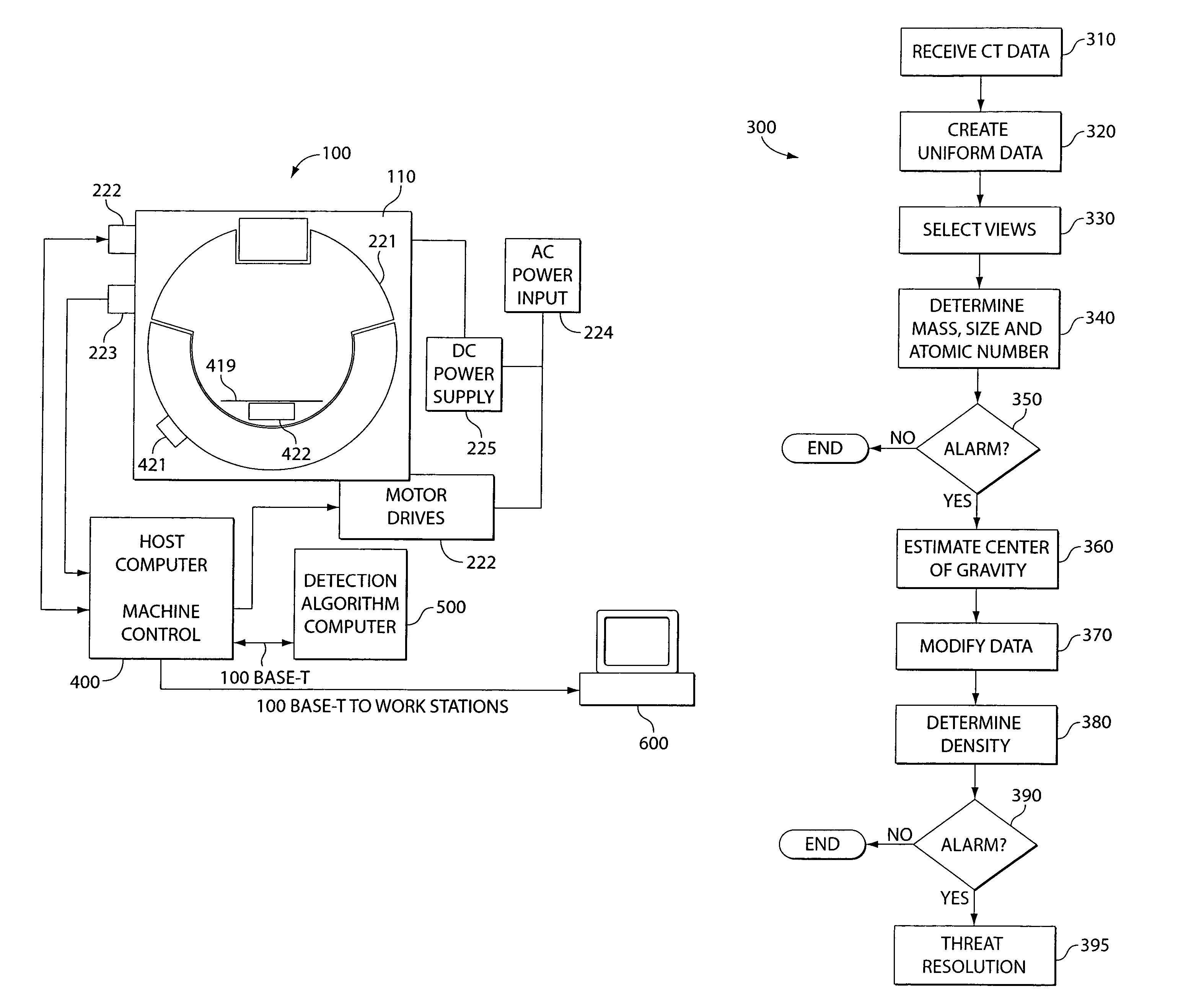
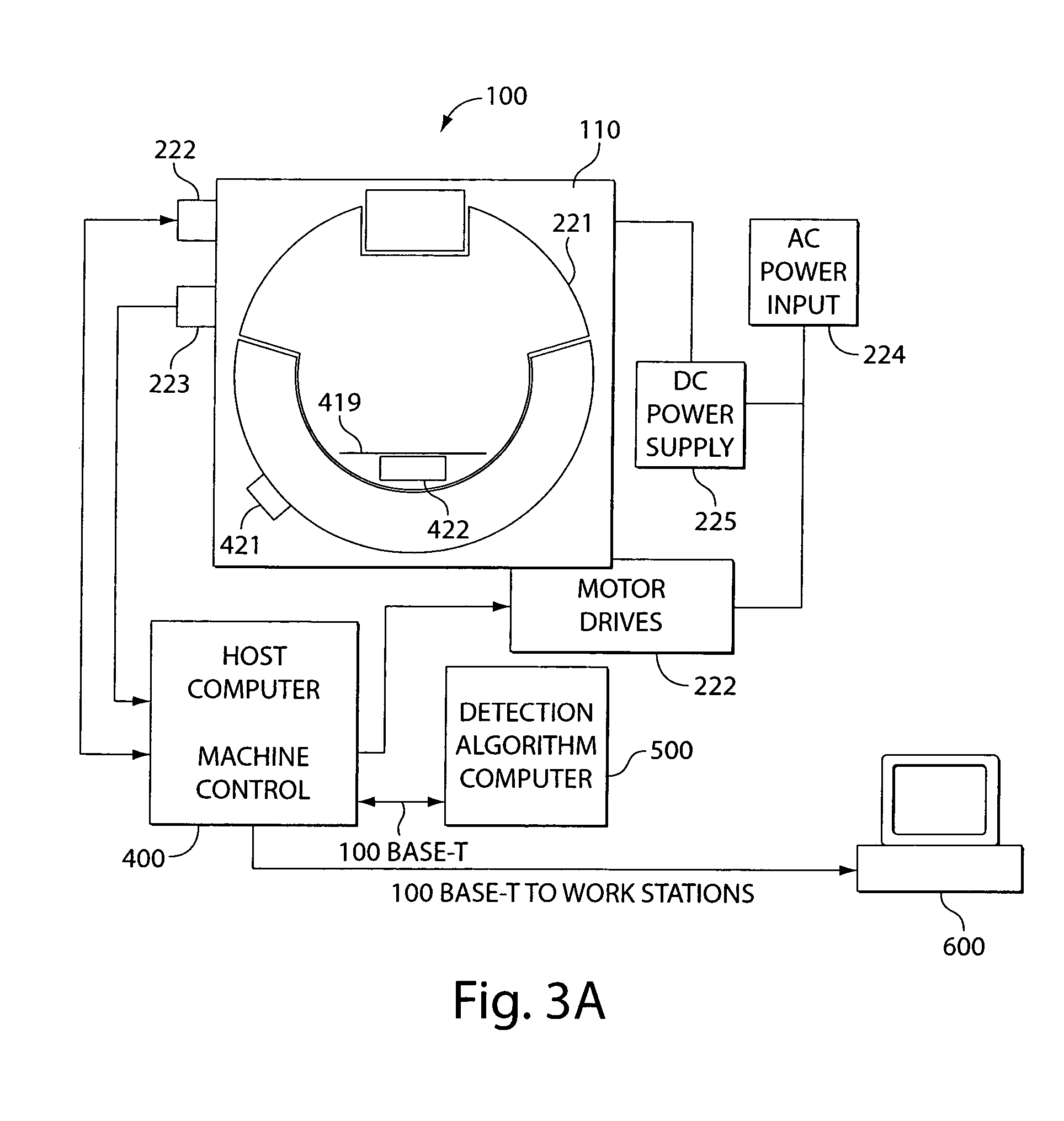
[0053]One embodiment of a system according to the invention includes a CT scanner that obtains CT data of a container, e.g., a bag. CT data may be obtained from a CT scanner of any known design. For example, the CT data may be obtained from a conventional CT scanner as shown in FIG. 1 and discussed above. In another embodiment, a system according to the invention can include a different CT scanner configuration such as that disclosed in U.S. patent application Ser. No. 10 / 677,967, entitled “Folded Array C...


PUM

PropertyMeasurementUnit
timeaaaaaaaaaa
timeaaaaaaaaaa
densityaaaaaaaaaa

Abstract

A system and method for baggage screening at security checkpoints. A CT scanner system processes x-ray data to locate and eliminate non-contraband without a full CT reconstruction of the entire bag. The CT scanner system utilizes lineogram data to disqualify objects of insufficient size, density, or mass as potential threats. Objects can be inspected with CT reconstruction. The CT scanner is capable of obtaining CT data and projection images. Multiple CT scanning systems can be multiplexed together, and each CT scanning system is in communication with a review station. Baggage scanning may also be based on security intelligence inputs such as CAPPS to increase throughput.

Description

CROSS REFERENCE TO RELATED APPLICATION[0001]This document claims priority to, and the benefit of the filing date of, provisional application entitled “Checkpoint CT Scanner System,” assigned Ser. No. 60 / 543,768, filed Feb. 11, 2004, and which is hereby incorporated by reference in its entirety.BACKGROUND OF THE INVENTION[0002]1. Field of the Invention[0003]The present invention relates to baggage inspection systems. More particularly, it relates to container, e.g., baggage, inspection systems and methods for detecting security threats.[0004]2. Discussion of Related Art[0005]Security checkpoints, such as those located in airports, screen people and packages for contraband, such as weapons or explosives. Various technologies are used at such checkpoints. Typically, individuals pass through metal detection devices. Projection x-ray systems screen baggage and packages. In current conditions of heightened security, passengers can experience long delays in passing through security checkpo...

Claims


Application Information

Patent Timeline
Patent Type & Authority Patents(United States)
IPC IPC(8): G01N23/04G01V5/00
CPCG01N23/046G01V5/005Y10S378/901G01N2223/419G01V5/226
Inventor SCHEINMAN, ELAN D.ELLENBOGEN, MICHAELBIJJANI, RICHARD ROBEHR
Owner REVEAL IMAGING TECH
Why Eureka
Try Eureka