
Tee baffle for use at inlet or outlet of septic and other on-site waste disposal systems

a technology for septic tanks and waste disposal systems, applied in the direction of filtration separation, branching pipes, separation processes, etc., can solve the problems of septic tanks, exposed portions of concrete baffles, and deterioration, and achieve material and molding expense savings, sufficient solvent room, and reduced wall thickness

Inactive Publication Date: 2008-10-21
TWM IP LLC
View PDF53 Cites 4 Cited by
  • Summary
  • Abstract
  • Description
  • Claims
  • Application Information

AI Technical Summary

Benefits of technology

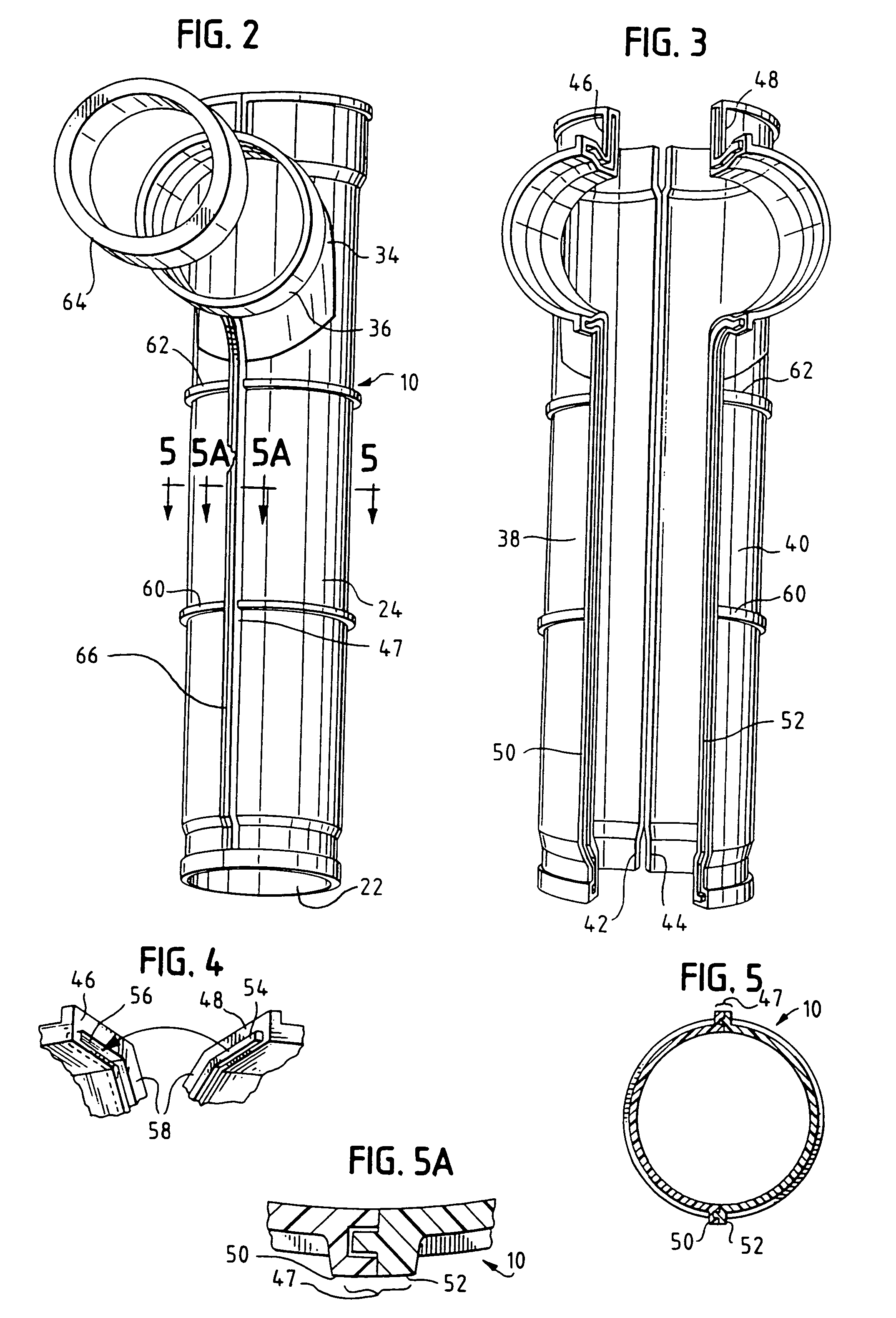
[0016]A preferably sanitary tee baffle, i.e., a tee having an arching sweep portion, is provided that is molded in one piece in one embodiment, or alternatively, in two distinct halves which are then mated with and rigidly fastened to one another, such that there are two seams longitudinally bisecting the resultant sanitary tee baffle. For reasons of brevity, the terms tee baffle and tee are used synonymously herein. Each of the mating halves of the sanitary tee baffle is in the shape of a lower case r, with an elongated main body portion extending substantially below the sweeping portion. In this manner, the sanitary tee baffle itself is of sufficient length to serve as a housing for an effluent filter, without the need for securement of additional lengths of pipe. The sanitary tee baffle of the present invention, whether formed of one or two pieces, is of reduced wall thickness over most of its length, as compared with conventional schedule 40 pipes and pipe tees, which generally have a wall thickness of about 0.250″. The reduced wall thickness, on the order of between 0.075″ and 0.100″, and preferably about 0.0901″, means a substantial savings in material and molding expense.
[0017]The two-piece sanitary tee baffle has a total of six mating edges, which extend between an inner slanted shoulder of the hub near the top of the sanitary tee baffle, an inlet / outlet port, and a lowermost end of the sanitary tee baffle. The inner slanted shoulder of the hub provides a stop for a cap of the effluent filter. The mating edges of one of the mating halves are provided with tongues extending substantially the length of each respective edge, and projecting perpendicularly from such respective edge. The tongues are received in grooves, respectively provided in each of the corresponding mating edges of the other mating half of the sanitary tee. Each of the mating edges are provided with smooth portions that extend outwardly of the tongues and grooves. The smooth portions provide additional surface area for solvent welding of the two mating halves, as well as providing elongated ridges on the outside of the sanitary tee for clamping the mating halves to one another during curing of the solvent. Preferably, there is a clearance fit, both width-wise and depth-wise, between the tongues and the grooves, so as to provide sufficient room for the solvent and to facilitate assembly.
[0018]The sanitary tee is also provided with one or more integral annular strengthening ribs on the outer wall to provide reinforcement to the otherwise thin walled thicknesses. The lower region of the tee includes a cylindrical portion that tapers inwardly down to a smaller diameter lowermost end of the tee. This lowermost end advantageously can be used to couple with the bell end of a length of additional pipe to further lengthen the sanitary tee, if needed. This would be advantageous because the thinner-walled pipe achieves what conventionally required Schedule 40 pipe. The inner wall of the lowermost end also provides an improved seal surface for the annular gaskets provided on many commercial single-pass type effluent filters.

Problems solved by technology

A drawback of concrete baffles is that the exposed portion thereof, i.e. that portion of the concrete baffles which is above the level of the scum layer within the septic tank, rapidly deteriorates.
As a result, such standard tees and sweep tees are not universally adequate for serving as the housing for an effluent filter inside the septic tank.
They are relatively heavy, and relatively expensive for use in septic systems.
Another drawback of conventional tees is the difficulty and expense of molding such tees.
Due to the necessity of having three openings and a hollow interior, complex molds are necessary to achieve a molded one-piece tee.
Most injection molding techniques presently used to manufacture pipe tees leave undesirable interior seams and flash, which tend to impede insertion of effluent filters into the pipe tees, and adversely effect operation and sealing of the effluent filters and pipe tees.
Also, because grease, fats, oils, hair, lint, and other floatables in effluent tend to collect at rough surfaces along the interior wall of a conventional pipe tee to thereby cause flow blockage, such seams or flash provide surfaces where such undesired waste products are likely to be deposited.
Over time, solid and semi-solid waste in the effluent will build up, and slime will grow at such seams or flash, the combination eventually prematurely plugging the pipe tee.
This undesirable plugging also detrimentally effects the needed sealing surfaces for the annular seals used with many prior art single-pass filters.
A recognized problem with conventional pipe tees used in on-site waste systems is that, once they start to become plugged, it is more difficult for the effluent to make its way through the pipe tee, through an effluent filter held therein, and out the outlet of the septic tank.
In many cases, these head pressures undesirably cause the effluent filters to literally pop up out of the pipe tees.
Since conventional pipe tees are formed as relatively short-length plumbing couplings, they are not of sufficient length to encase or house any of the currently available effluent filters.

Method used


Image

  • Tee baffle for use at inlet or outlet of septic and other on-site waste disposal systems
  • Tee baffle for use at inlet or outlet of septic and other on-site waste disposal systems
  • Tee baffle for use at inlet or outlet of septic and other on-site waste disposal systems

Examples


Embodiment Construction

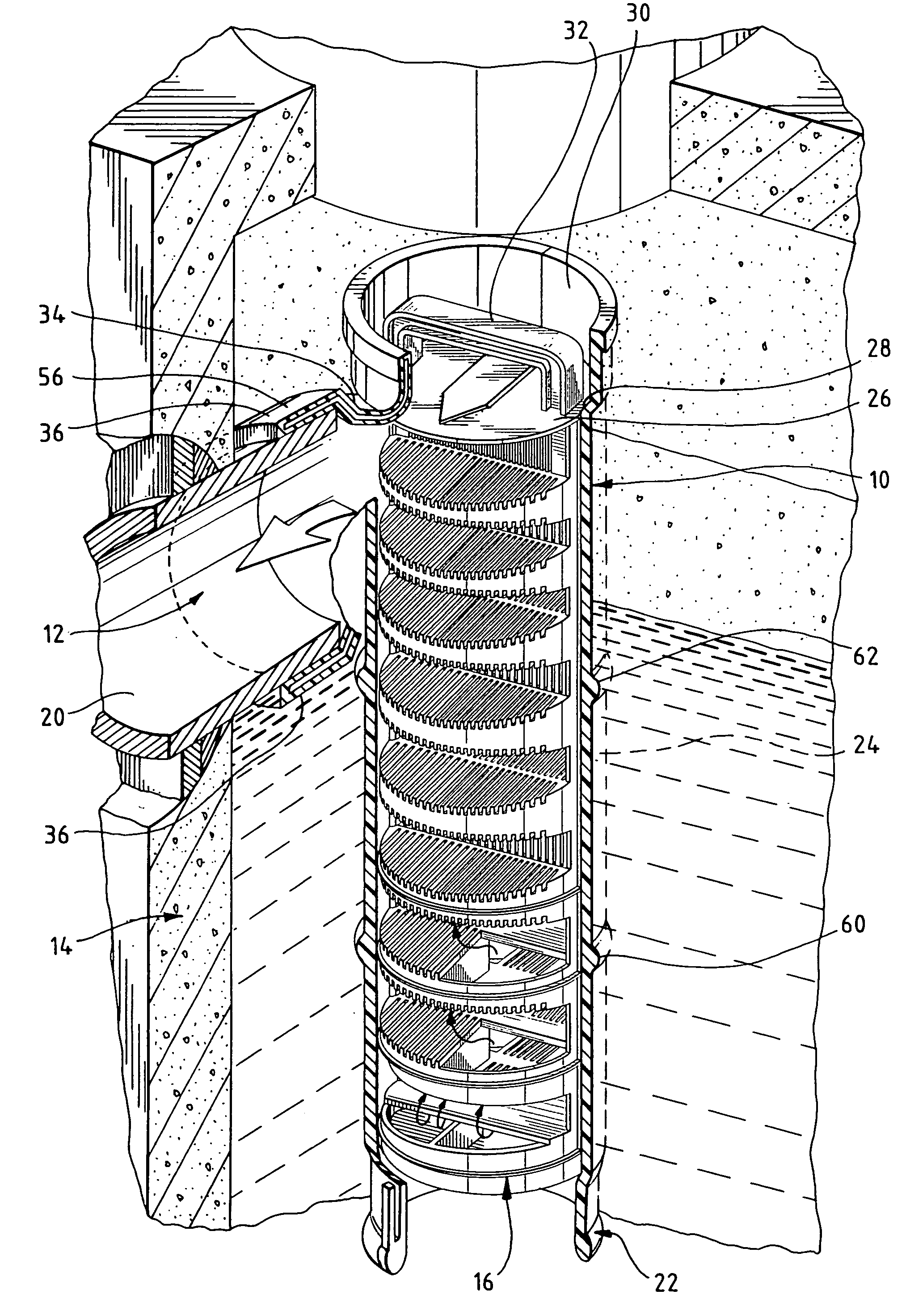
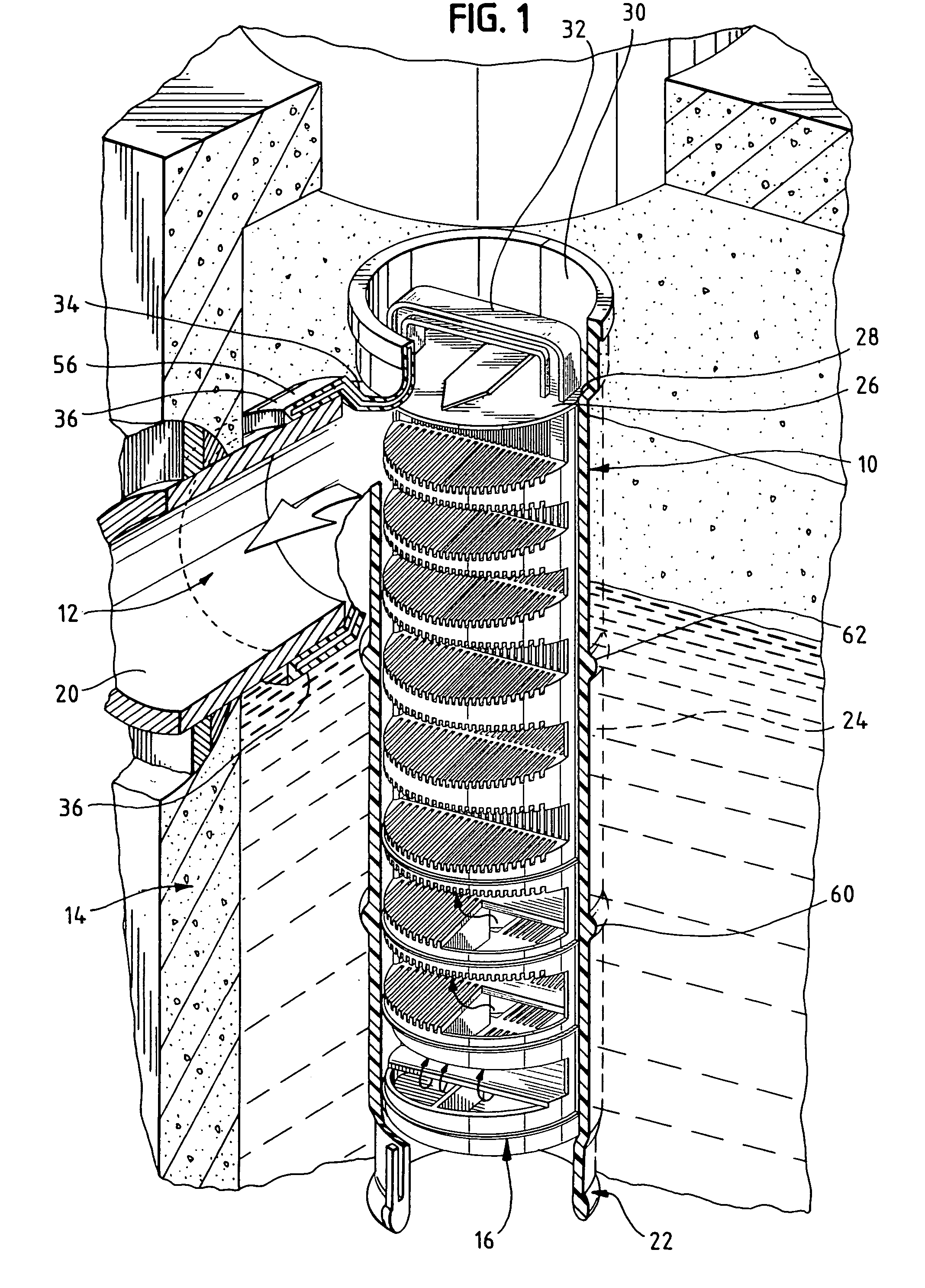
[0035]A sanitary tee 10 of the present invention is used at an outlet opening 12 of a septic tank 14, and can serve as a housing for an effluent filter 16, as shown in FIG. 1 as a multi-pass type effluent filter. Before exiting the septic tank 14 through a drainage pipe 20, effluent passes into a lowermost end 22 of the sanitary tee 10. The effluent then is filtered through the effluent filter 16 substantially occupying the hollow space in an elongated main body portion 24 of the sanitary tee 10. The cap 26 of the effluent filter 16 rests on a tapered rim 28, or inner slanted shoulder, at the intersection of the elongated main body portion 24 and a bell-shaped upper end or hub 30 of the sanitary tee 10.

[0036]The hub 30 is preferably in the form of a ring that is open at the top to allow for access to the handle 32 of the effluent filter 16, provided on a top side of the cap 28. The sanitary tee 10 further includes an arching sweep portion 34 that defines an opening in communication ...


PUM

PropertyMeasurementUnit
inner diameteraaaaaaaaaa
diameteraaaaaaaaaa
outer diameteraaaaaaaaaa

Abstract

A tee baffle for use at the inlet or outlet of a septic tank or other on-site waste drainage system has a thin-walled profile and is provided with ribs along its longitudinal axis and one or more annular ribs. The tee baffle has a lowermost end for accommodating the bell end or hub of a length of pipe to facilitate lengthening the tee to the desired dimension. The tee baffle can accommodate various sizes and types of effluent filters having generally cylindrical profiles, and may be provided with inwardly-directed flanges, tabs, or ribs to hold effluent filters in place and prevent an effluent filter from becoming dislodged from the tee baffle.

Description

BACKGROUND[0001]1. Field of the Invention[0002]The present invention relates generally to pipe fittings and, more particularly, to a tee provided at the inlet and / or outlet of a septic tank and other on-site waste disposal systems. The tee can be used as a housing for an effluent filter at the outlet of a septic tank, and can also be used without an effluent filter, in place of conventional pipe tees at the inlet of a septic tank.[0003]2. Background[0004]Most septic systems and other on-site waste disposal systems utilize pipe couplings, known in the art as so-called tees, for directing and controlling flow of sewage into, or effluent out of, the tank of the disposal system. Older concrete septic systems utilized cast-in concrete baffles at the inlet and outlet of the system. A drawback of concrete baffles is that the exposed portion thereof, i.e. that portion of the concrete baffles which is above the level of the scum layer within the septic tank, rapidly deteriorates. This is und...

Claims


Application Information

Patent Timeline
Patent Type & Authority Patents(United States)
IPC IPC(8): F16L39/00F16L39/04
CPCF16L41/021B01D35/0276E03F11/00Y02A20/208
Inventor MEYERS, THEODORE W.
Owner TWM IP LLC
Learn More