Laser scanner

a laser scanner and scanner technology, applied in optics, instruments, electrical equipment, etc., can solve the problems of user restricting the use of the most expensive and high-quality modules to applications, less expensive modules are exposed to damage risk, etc., to achieve a higher spatial measurement range, relatively low purchase price, and high mechanical or electronic quality

Active Publication Date: 2008-09-30
FARO TECH INC
View PDF3 Cites 151 Cited by
  • Summary
  • Abstract
  • Description
  • Claims
  • Application Information

AI Technical Summary

Benefits of technology

[0012]With a laser scanner according to the present invention, a user may, namely, in the first place purchase a model in which the various components are in the lowermost range of specifications such that the purchase price is relatively low. When the requirements of the user develop positively, for example in that a higher spatial measuring range or, alternately, a higher mechanical or electronic quality and, concurrently a higher precision of the measurement is required, then the user may make a decision to replace only some of the scanner modules, while other modules may still continue to be used. It is, thus, possible to upgrade the scanner into a higher class of specifications at lower costs as compared to conventional laser scanners where an upgrade necessitated the purchase of an entirely new instrument.
[0040]This measure has the advantage that all modules or any given sub-combination of modules may interact electronically, wherein the interconnection of the modules involved may simply be effected by plugging.

Problems solved by technology

For example, if there are only moderate requirements for a specific measuring task, then the laser scanner may be equipped with modules from the lowermost range only such that in case of a measurement to be performed under rough external conditions bearing the risk of a damage during the measurement, only the less expensive modules are exposed to the risk of damage.
The user may restrict the use of the most expensive and high-quality modules to applications with the highest requirements e.g. to the spatial measuring range and the precision of measuring results.

Method used


Image

  • Laser scanner
  • Laser scanner
  • Laser scanner

Examples


Embodiment Construction

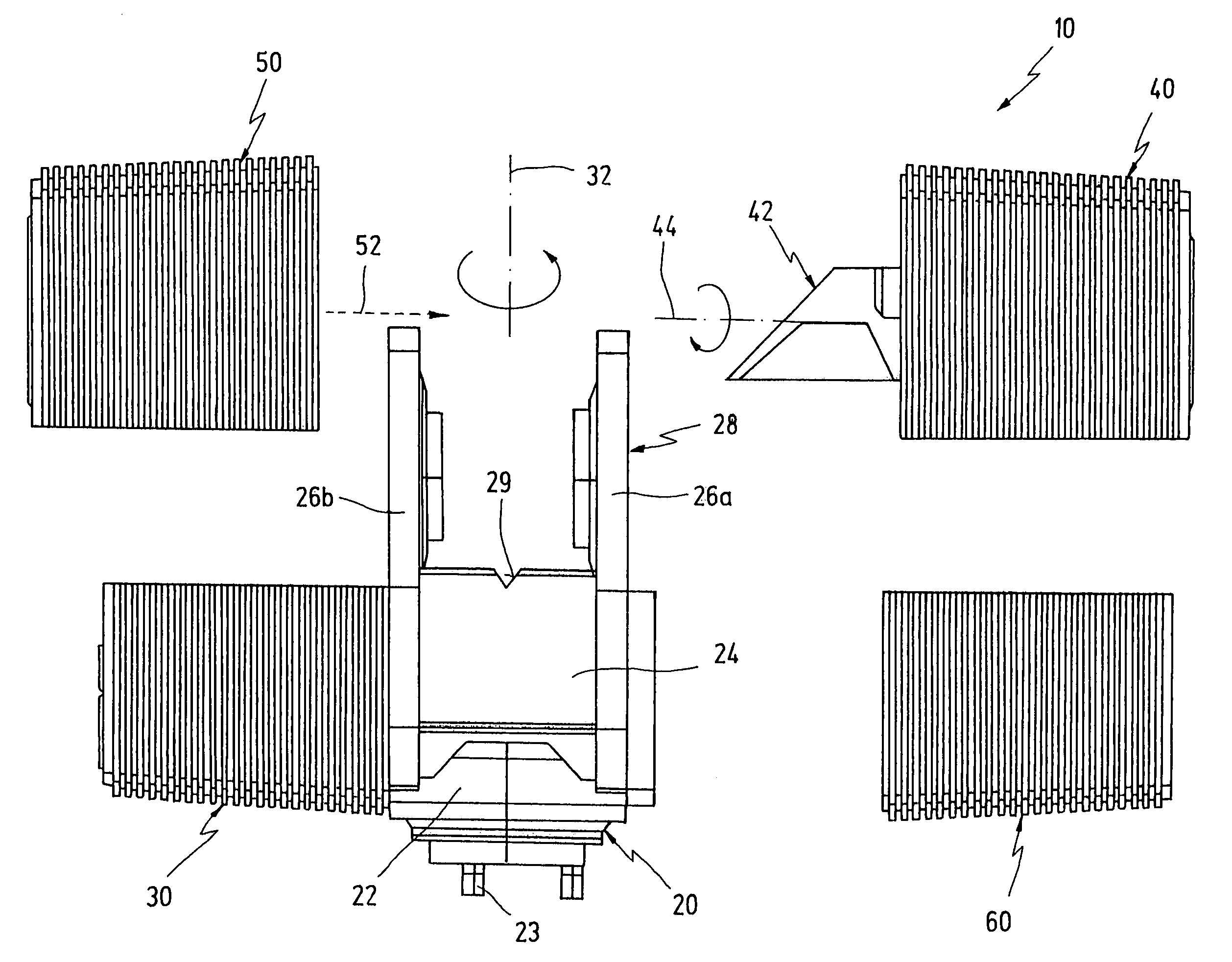
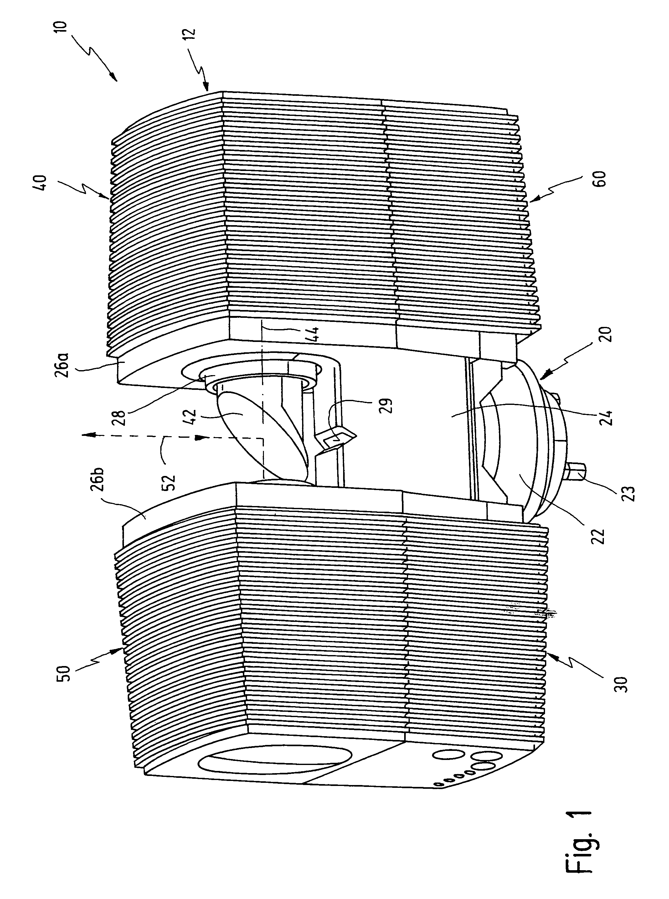
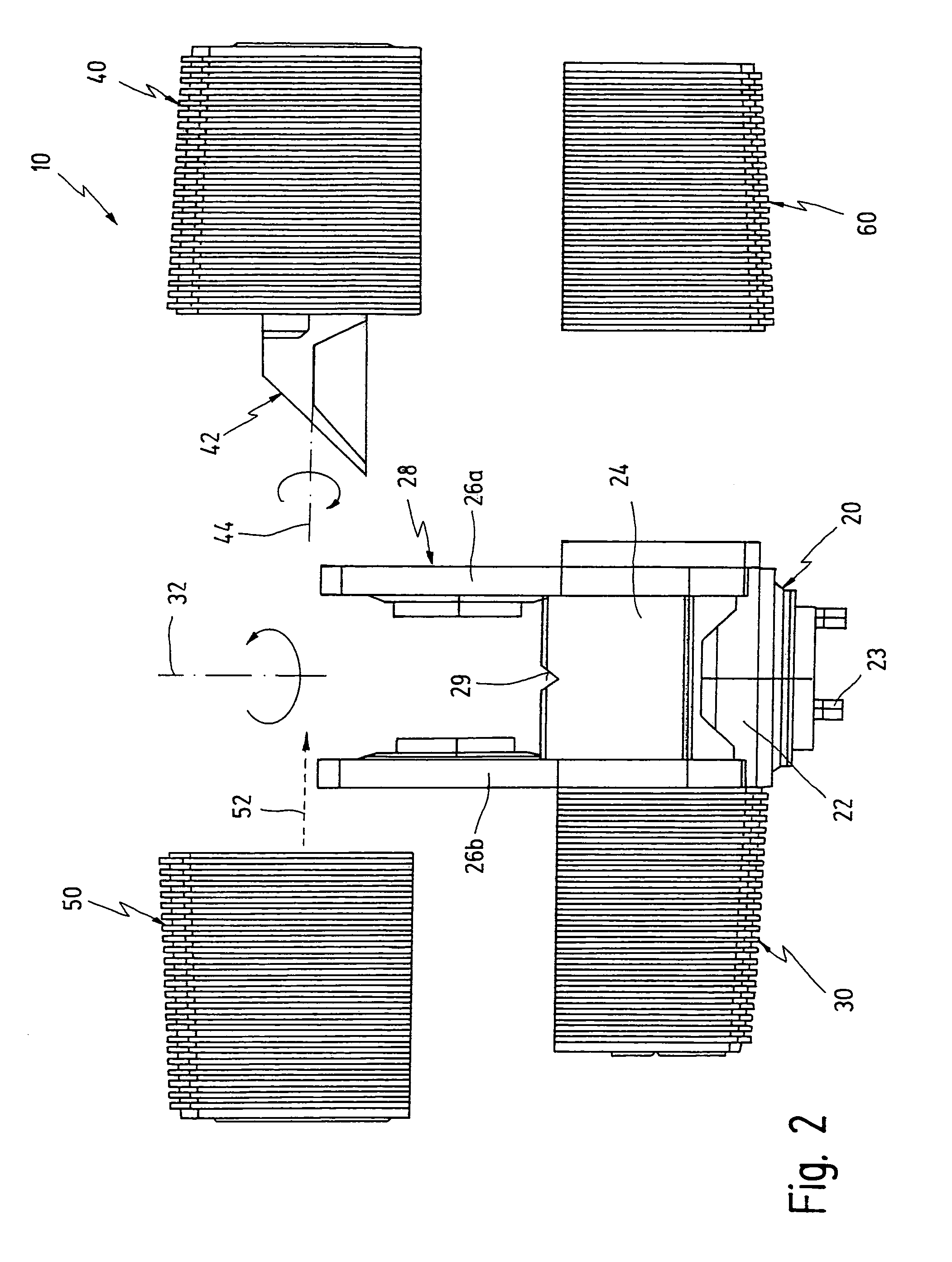
[0046]In the figures, reference numeral 10 as a whole denotes a laser scanner having a measuring head 12 conventionally arranged e.g. on a tripod (not shown). The measuring head 12 consists of five modules 20, 30, 40, 50 and 60.

[0047]A first module 20 is a rotary unit. First module 20 houses a base 22 held stationary under normal operational conditions. Base 22 has standardized pegs 23 or vertically adjustable feet as well as a bubble level (not shown). Standardized pegs 23 may be adapted to commercially available tripods to enable an easy click-connection with laser scanner 10. A rotor 24 is located on base 22. Rotor 24 has lateral legs 26a, 26b preferably integral with its support structure. Legs 26a, 26b extend parallel, vertical and at a distance from each other. Right hand leg 26b in FIGS. 1 and 2 has a through-opening 28 for a rotary mirror, as will be explained below. A reference mark 29 configured as a notch is provided in the central range of rotor 24 bridging legs 26a and ...


PUM


Abstract

A laser scanner has a first axis and a second axis extending essentially transversely to the first axis. A measuring head is adapted to be rotated about the first axis. The measuring head has at least a first, a second, and a third module, wherein at least the first module and the third module are releasably connected to each other. A first rotary drive for rotating said measuring head is comprised within the first and the second modules. A rotary mirror is adapted to be rotated about the second axis. The rotary mirror is comprised within the third module. A second rotary drive is provided for rotating the rotary mirror. The second drive is likewise comprised within the third module. A transmitter is provided in the measuring head for transmitting a light beam. A receiver is provided in the measuring head for receiving the light beam after a reflection thereof by an object located at a distance from the laser scanner. A computer is provided in the measuring head for processing signals embedded within the received light beam.

Description

FIELD OF THE INVENTION[0001]The present invention relates to the field of 3D laser scanners.[0002]More specifically, the present invention relates to the field of 3D laser scanners having a measuring head adapted to be rotated about a first axis, a first rotary drive for rotating the measuring head, a rotary mirror adapted to be rotated about a second axis extending essentially transversely to the first axis, a second rotary drive for rotating the rotary mirror, a transmitter arranged in the measuring head for transmitting a light beam, a receiver arranged in the measuring head for receiving the light beam after a reflection thereof by an object located at a distance from the laser scanner, and a computer arranged in the measuring head for processing signals embedded within the received light beam.BACKGROUND OF THE INVENTION[0003]Laser scanners of the type specified above are commercially available, e.g. under the trade name “iQsun 625” from the assignee of the present application.[...

Claims


Application Information

Patent Timeline
Patent Type & Authority Patents(United States)
IPC IPC(8): H04N1/46H04N1/04G02B26/10
CPCG02B26/10G01S7/4813
Inventor BECKER, REINHARDBECKER, BERND-DIETMAR
Owner FARO TECH INC
Why Eureka
Try Eureka