
Balanced acoustic wave filter

a filter device and acoustic wave technology, applied in the direction of impedence networks, electrical devices, etc., can solve the problems of unbalanced signals of antenna inputs and outputs, unbalanced-balanced conversion functions of components, unbalanced-balanced conversion functions of surface acoustic wave filters, etc., to achieve a higher ratio of impedance of balanced terminals

Active Publication Date: 2008-09-30
MURATA MFG CO LTD
View PDF28 Cites 10 Cited by
  • Summary
  • Abstract
  • Description
  • Claims
  • Application Information

AI Technical Summary

Benefits of technology

The present invention provides an acoustic wave filter device with a balanced-unbalanced conversion function and a high-ratio impedance conversion function. The device includes a piezoelectric substrate and acoustic wave filter units of a longitudinally coupled resonator type. The first and second acoustic wave filter units are connected to the unbalanced terminal and the first and second balanced terminals, respectively. The first and second IDTs are connected electrically in series, while the second and fourth IDTs are connected electrically in series. The device also includes outermost electrode fingers connected to ground, and the impedance of the unbalanced terminal is different from the impedance of the balanced terminals. The invention provides an improved acoustic wave filter device with improved performance and reliability.

Problems solved by technology

In this case, the antenna inputs and outputs unbalanced signals, while the differential amplifier inputs and outputs balanced signals.
Therefore, it is necessary to insert a component having an unbalanced-balanced conversion function between the antenna and the differential amplifier.
Therefore, surface acoustic wave filters having a balanced-unbalanced conversion function must also provide an impedance conversion function.

Method used


Image

  • Balanced acoustic wave filter
  • Balanced acoustic wave filter
  • Balanced acoustic wave filter

Examples


Embodiment Construction

[0040]Preferred embodiments of the present invention will now be described with reference to the drawings.

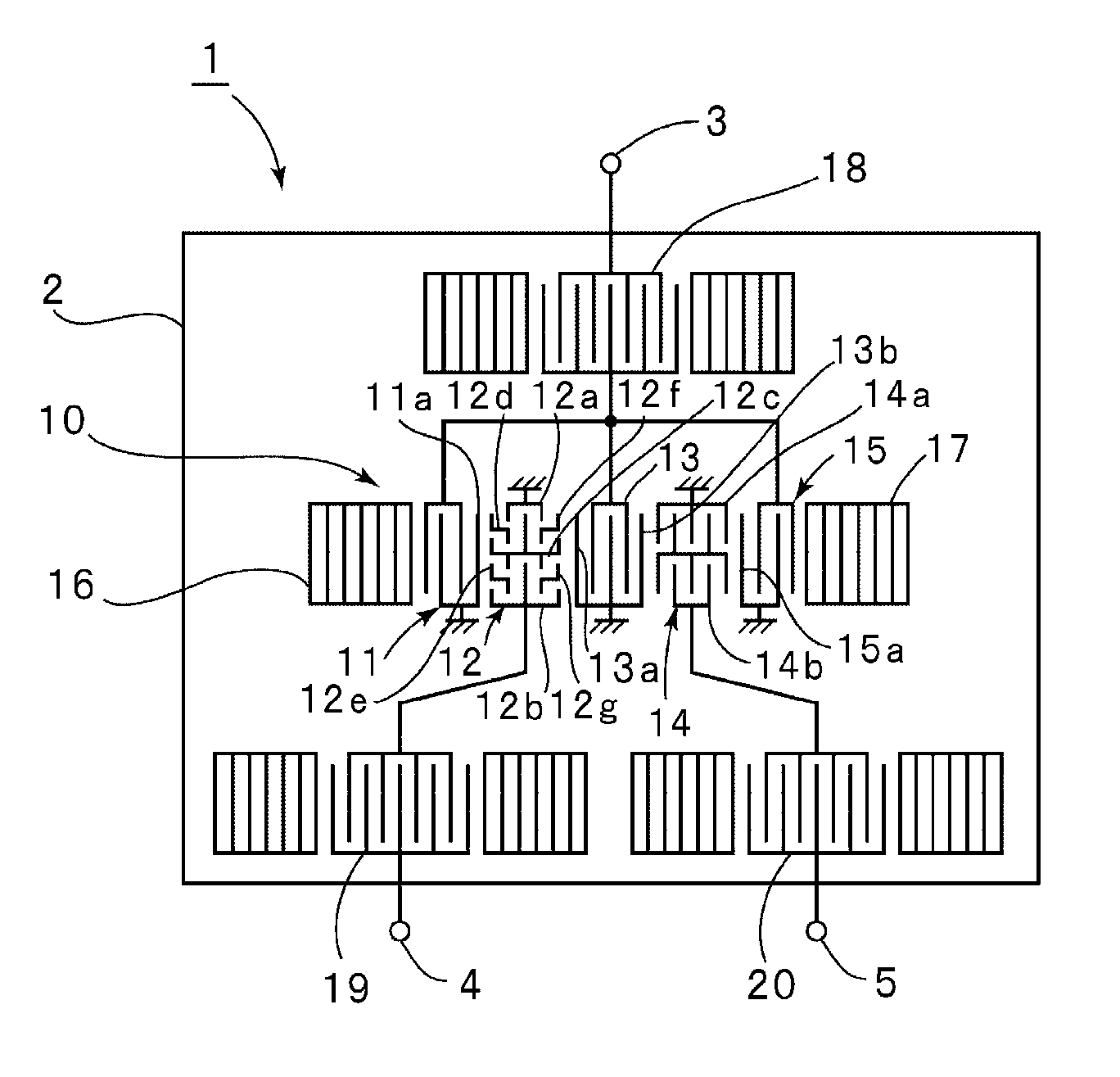
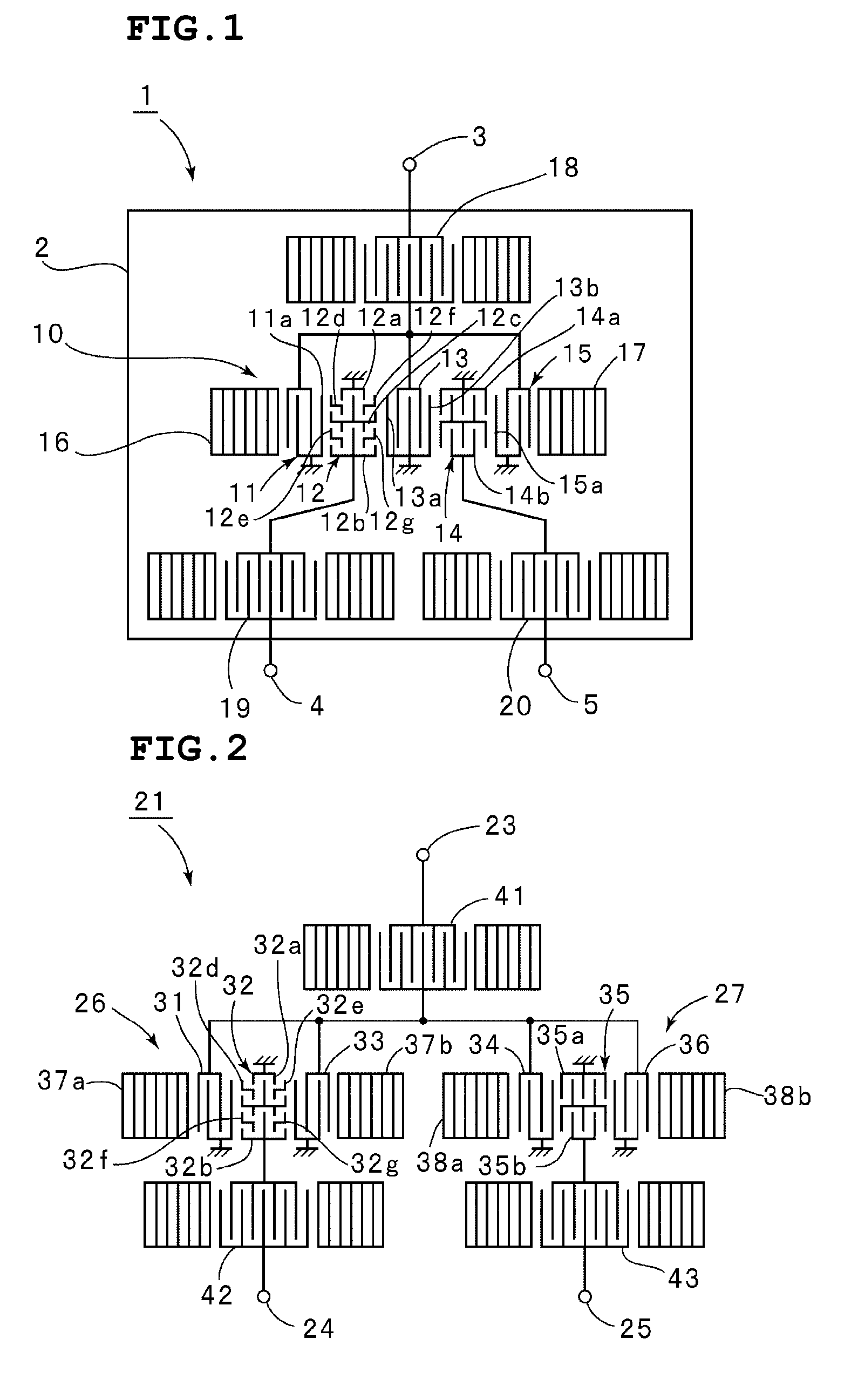
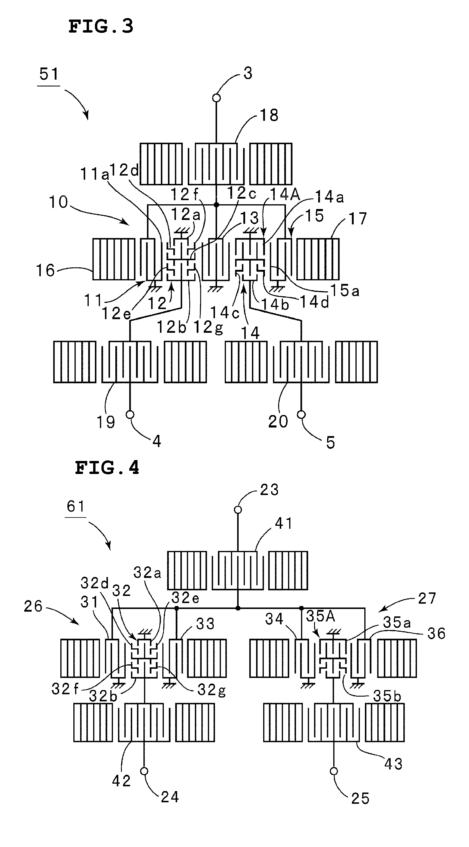
[0041]FIG. 1 is a schematic plan view of a surface acoustic wave filter device according to a first preferred embodiment of the present invention. A surface acoustic wave filter device 1 of the present preferred embodiment is preferably a five-IDT longitudinally coupled resonator surface acoustic wave filter device.

[0042]The surface acoustic wave filter device 1 includes a piezoelectric substrate 2 preferably made of a piezoelectric single crystal, such as LiTaO3, LiNbO3, or quartz, or piezoelectric ceramics. The piezoelectric substrate 2 may have a structure in which a piezoelectric thin film is provided on a substrate of piezoelectric material or on an insulating substrate.

[0043]The surface acoustic wave filter device 1 of the present preferred embodiment is a balanced surface acoustic wave filter device having a balanced-unbalanced conversion function and includes an unbalanc...


PUM


Abstract

An acoustic wave filter device includes a piezoelectric substrate and a longitudinally coupled resonator surface acoustic wave filter unit provided on the piezoelectric substrate. The surface acoustic wave filter unit includes first to fifth IDTs arranged in a surface wave propagation direction. The first, third, and fifth IDTs are connected to an unbalanced terminal, while the second and fourth IDTs are connected to first and second balanced terminals, respectively. The second IDT includes first and second sub-IDT portions obtained by dividing the second IDT and arranged in a crossing width direction, and the fourth IDT includes first and second sub-IDT portions obtained by dividing the fourth IDT and arranged in the crossing width direction. The first and second sub-IDT portions are connected in series. The first and second sub-IDT portions are also connected in series.

Description

BACKGROUND OF THE INVENTION[0001]1. Field of the Invention[0002]The present invention relates to a balanced acoustic wave filter device having a balanced-unbalanced conversion function.[0003]2. Description of the Related Art[0004]A surface acoustic wave filter is often provided in mobile communication equipment as a band-pass filter between an antenna and a differential amplifier. In this case, the antenna inputs and outputs unbalanced signals, while the differential amplifier inputs and outputs balanced signals. Therefore, it is necessary to insert a component having an unbalanced-balanced conversion function between the antenna and the differential amplifier. If a surface acoustic wave filter having a balanced-unbalanced conversion function is used as a band-pass filter, a component which provides a balanced-unbalanced conversion function, that is, a balun, can be eliminated. Accordingly, various types of balanced surface acoustic wave filters having a balanced-unbalanced conversi...

Claims


Application Information

Patent Timeline
Patent Type & Authority Patents(United States)
IPC IPC(8): H03H9/64
CPCH03H9/0038H03H9/0071H03H9/14591H03H9/14532H03H9/02748
Inventor SHIBAHARA, TERUHISA
Owner MURATA MFG CO LTD
Learn More