
Working fluids for thermal energy conversion of waste heat from fuel cells using Rankine cycle systems

a technology of working fluids and waste heat, which is applied in the direction of sustainable manufacturing/processing, machines/engines, lighting and heating apparatus, etc., can solve the problems of difficult load matching, environmental risk, and confusion of the efficient operation of the combined heat and power system

Active Publication Date: 2008-09-30
HONEYWELL INT INC
View PDF32 Cites 97 Cited by
  • Summary
  • Abstract
  • Description
  • Claims
  • Application Information

AI Technical Summary

Benefits of technology

The patent describes a process for recycling waste heat by using a liquid phase working fluid to convert the heat into mechanical energy. The working fluid is a compound that has a specific formula and can be selected from a variety of options. The process involves heating the working fluid, removing the vapor phase fluid, and using an expander to convert the vapor phase fluid to a liquid phase fluid. The liquid phase fluid is then returned to the process that produced the waste heat through a pump. The recovered heat can be used in various applications such as fuel cells, internal combustion engines, and refrigeration systems. The process is efficient and effective in recycling waste heat.

Problems solved by technology

Although these materials were non-flammable, they were a risk to the environment because of their ozone-depletion potential.
The most difficult case is when the thermal requirement is variable and load matching becomes difficult, confounding efficient operation of the combined heat and power system.
In many cases, load matching can be difficult to accomplish.
Some fuel cell designs, such as proton exchange membrane types, do not generate significantly high temperatures, around 100° C. or so, and would not have adequate levels of thermal energy for use of organic Rankine cycle.

Method used


Image

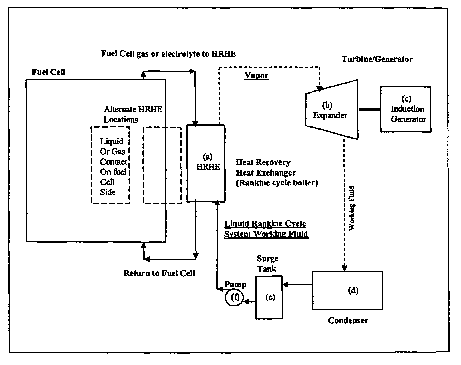
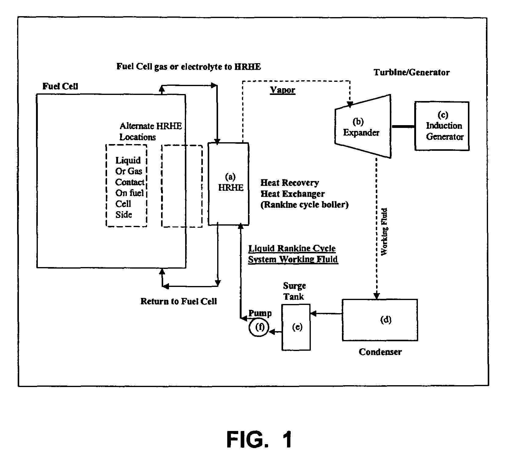
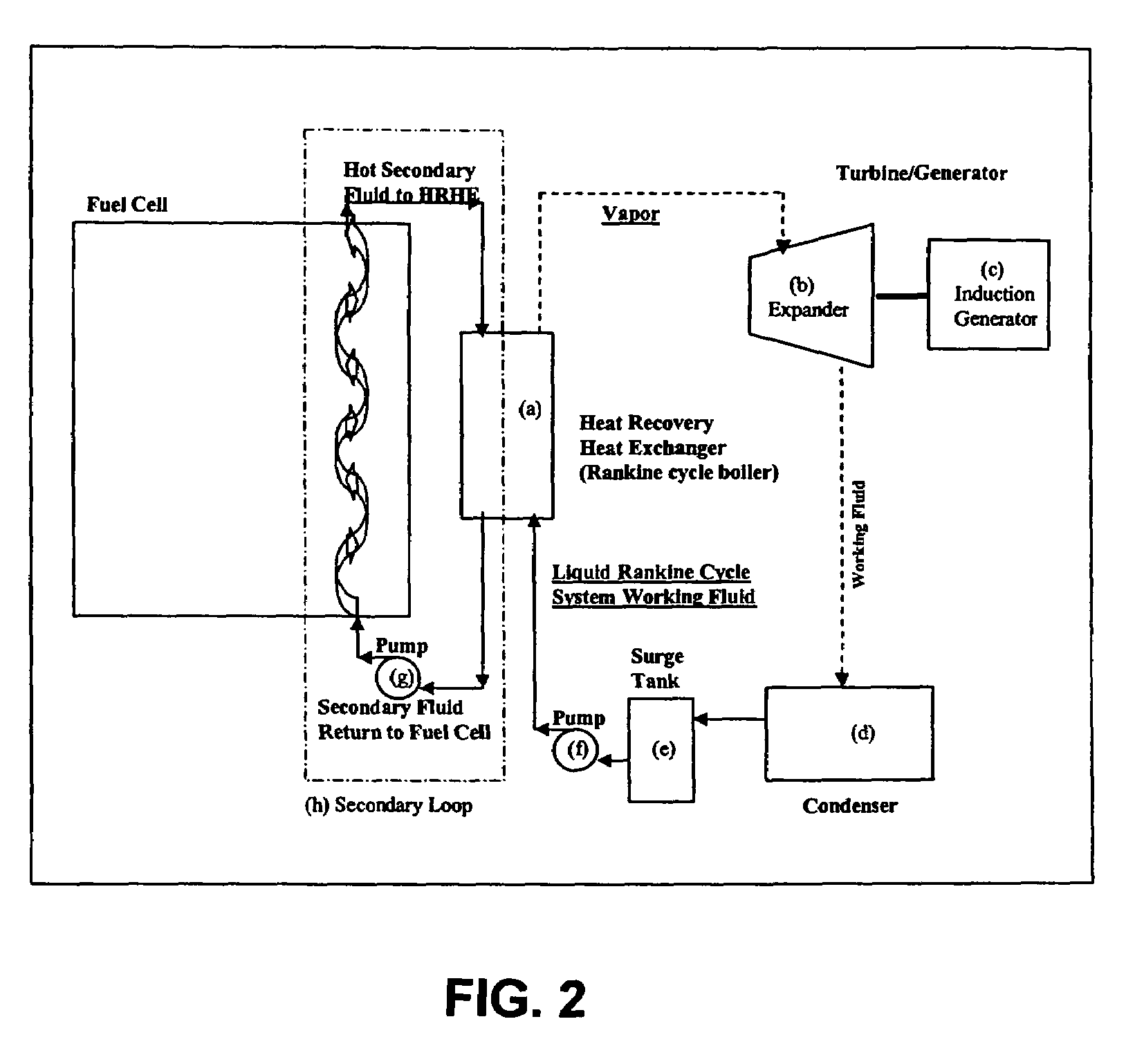
  • Working fluids for thermal energy conversion of waste heat from fuel cells using Rankine cycle systems
  • Working fluids for thermal energy conversion of waste heat from fuel cells using Rankine cycle systems
  • Working fluids for thermal energy conversion of waste heat from fuel cells using Rankine cycle systems

Examples


example 1

Optimize Cycle Efficiency for a Sub-Critical Organic Rankine Cycle

[0071]In organic Rankine cycle thermal to mechanical energy applications, increased cycle efficiency can be shown to be possible if the working fluid is properly matched to the source and sink temperature. To arrive, at the net work output, the absolute value of the enthalpy gain in the pump due to the increase in pressure in going from the condensing condition back to the boiler condition is subtracted from the absolute value of the difference in enthalpy values at the expander entrance (boiler exit) and expander exit. Dividing “net work output” by “heat input” to the boiler provides the cycle efficiency. The cycle efficiency is strongly dependent upon how far apart the source and sink temperatures are; increasing efficiency with greater temperature difference between source and sink. Moreover, for any given source and sink temperature set, cycle efficiency is increased by minimizing the temperature difference betwee...

example 2

Work Output at Cycle Efficiency away from Optimum, Organic Rankine Cycle Process

[0073]One way to assess the relative “goodness” of organic Rankine cycle working fluids is to compare theoretical cycle efficiency. However, many organic Rankine cycle systems utilize waste heat as the driver, hence cycle efficiency is typically not as important as the net work derived (work extracted during expansion less work of the pump). When an organic Rankine cycle is plotted on a temperature entropy diagram, the net work is related to the area under the curve traced out by the Rankine cycle (shaded area shown in FIG. 3). The amount of net work that a fluid can produce increases as the two-phase dome becomes broader (the heat capacity of the fluid increases) and as the critical temperature increases. The temperature versus entropy relationships are plotted for 4-trifluoromethyl-1,1,1,3,5,5,5-heptafluoro-2-pentene ((CF3)2CHCF═CHCF3) and HFC-245fa in Table 1. Table 1 shows that 4-trifluoromethyl-1,1,...


PUM


Abstract

A process for recovering waste heat which comprises: (a) passing a liquid phase working fluid through a heat exchanger in communication with a process which produces the waste heat; (b) removing a vapor phase working fluid from the heat exchanger; (c) passing the vapor phase working fluid to an expander, wherein the waste heat is converted into mechanical energy; and (d) passing the vapor phase working fluid from the expander to a condenser, wherein the vapor phase working fluid is condensed to the liquid phase working fluid. The preferred working fluid is an organic Rankine cycle system working fluid comprising compounds having the following general structure:where x, y, z, and m are each selected from the group consisting of: fluorine, hydrogen, Rf, and R, wherein R and Rf are each an alkyl, aryl, or alkylaryl of 1 to 6 carbon atoms, and wherein Rf is partially or fully fluorinated.

Description

BACKGROUND OF THE INVENTION[0001]1. Field of the Invention[0002]The present invention generally relates to novel working fluids uniquely designed for higher cycle efficiencies, thereby leading to higher overall system efficiencies and therefore lower fuel consumption and lower emissions levels. In particular, these working fluids are useful in Rankine cycle systems for efficiently converting waste heat generated from industrial processes, such as electric power generation from fuel cells, into mechanical energy.[0003]2. Discussion of the Background Art[0004]Rankine cycle systems are known to be a simple and reliable means to convert heat energy into mechanical shaft power. Organic working fluids are useful in place of water / steam when low-grade thermal energy is encountered. Water / steam systems operating with low-grade thermal energy (typically 400° F. and lower) will have associated high volumes and low pressures. To keep system size small and efficiency high, organic working fluid...

Claims


Application Information

Patent Timeline
Patent Type & Authority Patents(United States)
IPC IPC(8): F01K25/08
CPCC09K5/045F01K25/08H01M8/04022H01M8/04029Y02B90/16H01M2250/405Y02E60/50Y02B90/10Y02P20/10C09K5/04F25B9/00
Inventor SINGH, RAJIV RWILSON, DAVID PZYHOWSKI, GARY JHULSE, RYAN
Owner HONEYWELL INT INC
Learn More