Positively retained cap for use on an encapsulated anchor of a post-tension anchor system

Active Publication Date: 2008-09-16
SORKIN FELIX L
View PDF8 Cites 48 Cited by
  • Summary
  • Abstract
  • Description
  • Claims
  • Application Information

AI Technical Summary

Benefits of technology

[0029]In the present invention, the rigid ring is of a steel material. The polymeric encapsulation is in injection-molded relationship around the exterior surface of the rigid ring. The notch includes a first notch formed around the inner wall of the rigid ring adjacent an end of the rigid ring opposite the end surface of the anchor member. In an alternative form of the present invention, the notch includes a second notch formed around the inner wall of the rigid ring adjacent an opposite end of the rigid ring. This second notch is in spaced parallel relationship to the first notch. The rigid ring has a tapered surface at an end thereof adjacent an end of the tubular section of the polymeric encapsulation opposite the end surface of the anchor member. This tapered surface facilitates the ability to insert the periphery of the cap so as to engage the notch.

Problems solved by technology

On the other hand, structural concrete, though quite capable of carrying almost any compressive (vertical) load, is extremely weak in carrying significant tensile loads.
Structures of reinforced concrete may be constructed with load-bearing walls, but this method does not use the full potentialities of the concrete.
Metallic components within concrete structures may become exposed to many corrosive elements, such as de-icing chemicals, sea water, brackish water, or spray from these sources, as well as salt water.
If this occurs, and the exposed portions of the anchor suffer corrosion, then the anchor may become weakened due to this corrosion.
The deterioration of the anchor can cause the tendons to slip, thereby losing the compressive effects on the structure, or the anchor can fracture.
In addition, the large volume of by-products from the corrosive reaction is often sufficient to fracture the surrounding structure.
These elements and problems can be sufficient so as to cause a premature failure of the post-tensioning system and a deterioration of the structure.
The combination represents a relatively complicated configuration for a sealing cap wherein various locking fingers and a specially shaped sealing ring are necessary in an effort to seal the wedge cavity of the anchor from external contaminants.
Unfortunately, this device could be easily dislodged or improperly placed.
It is also possible that the cap could be improperly installed and this improper installation would not be noticeable upon inspection.
Unfortunately, with this prior art, the cap 12 is not “positively” attached within the tubular section 24 of the polymeric encapsulation 22 of anchor 14.

Method used


Image

  • Positively retained cap for use on an encapsulated anchor of a post-tension anchor system
  • Positively retained cap for use on an encapsulated anchor of a post-tension anchor system
  • Positively retained cap for use on an encapsulated anchor of a post-tension anchor system

Examples


Embodiment Construction

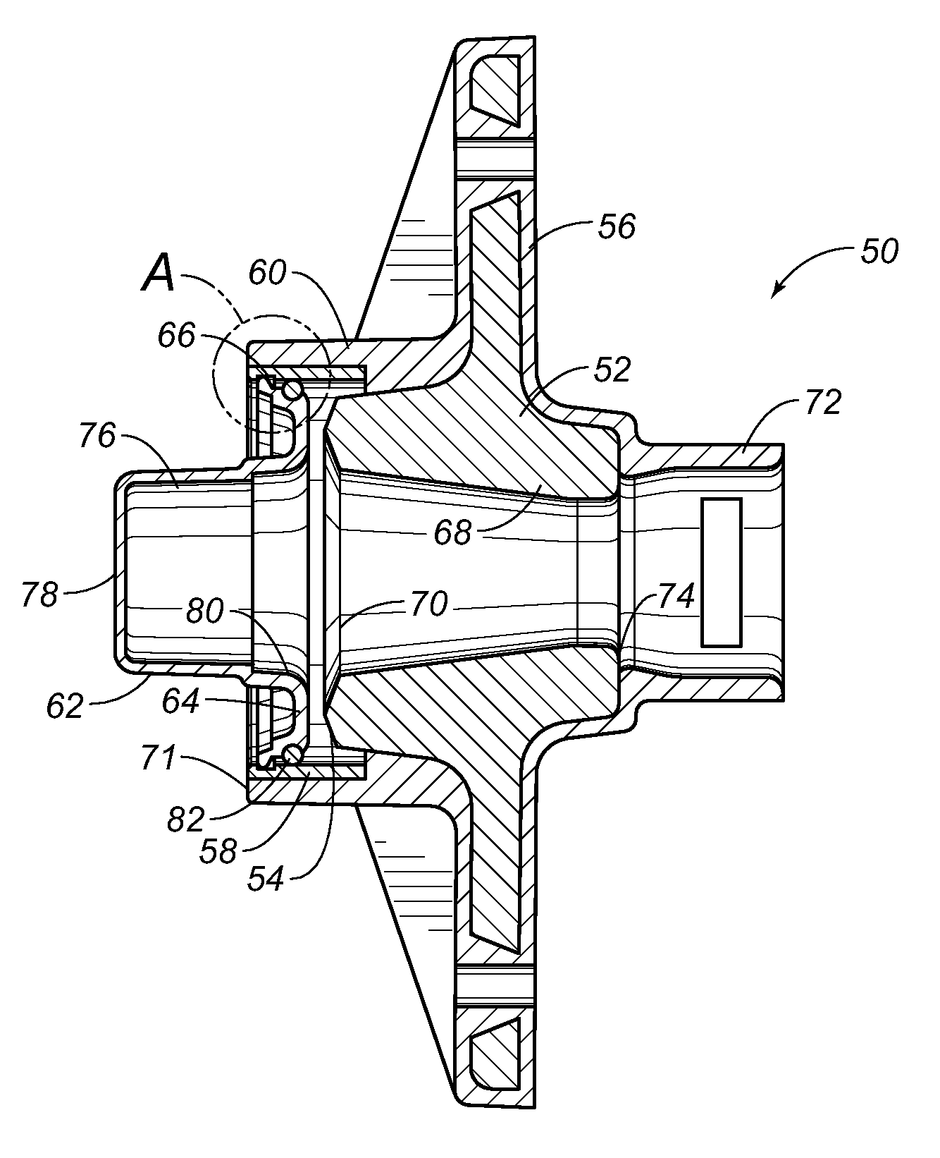
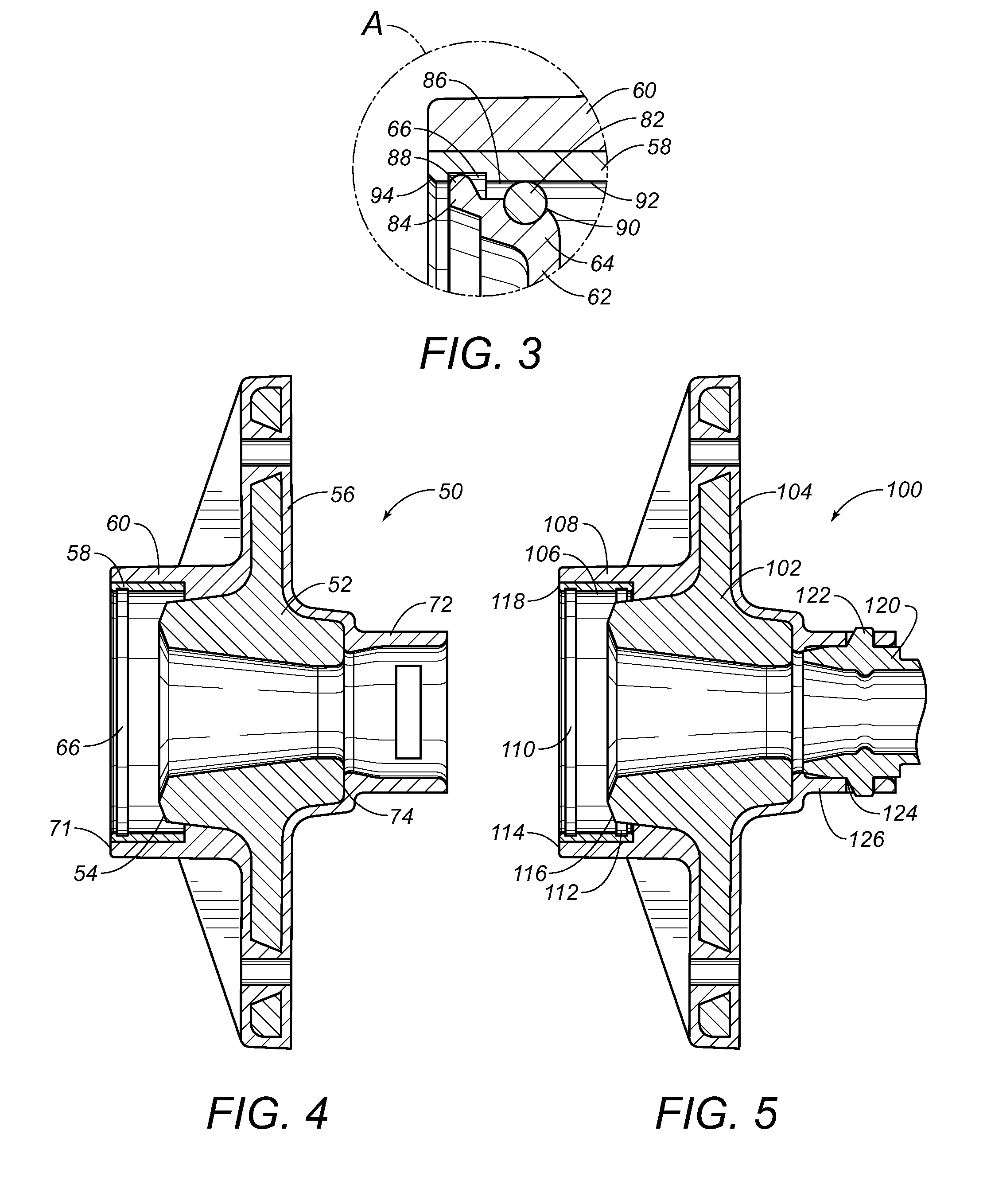
[0041]Referring to FIG. 2, there is shown the anchor assembly 50 as used in a post-tension anchor system in accordance with the teachings of the present invention. The anchor assembly 50 includes an anchor member 52 having an end surface 54, a polymeric encapsulation 56 coving the anchor member 52, a rigid ring 58 affixed within a tubular section 60 of the encapsulation 56, and a cap 62 having a flanged end 64 with an outer periphery engaged with a notch 66 of the rigid ring 58.

[0042]As can be seen in FIG. 2, the anchor member 52 is configuration similar to the anchor member as used within the prior art of FIG. 1. The anchor member 52 has a wedge cavity 68 of a tapered configuration formed centrally thereof. The end surface 58 defines the opening 70 of the wedge cavity 68 so as to allow wedges to be inserted for friction-fit engagement with the outer surface of a tendon extending therethrough.

[0043]The polymeric encapsulation 56 extends around the outer surfaces of the anchor member...


PUM


Abstract

An anchor assembly for a post-tension system has an anchor member, a polymeric encapsulation covering the anchor member and defining a tubular section extending outwardly of an end surface of the anchor member, a rigid ring affixed within this tubular section and having a notch formed in an inner wall thereof, and a cap having a generally tubular body with an open end and a closed end. The cap has a flanged end adjacent the open end thereof. This flanged end has an outer periphery engageable within the notch of the rigid ring.

Description

RELATED U.S. APPLICATIONS[0001]Not applicable.STATEMENT REGARDING FEDERALLY SPONSORED RESEARCH OR DEVELOPMENT[0002]Not applicable.REFERENCE TO MICROFICHE APPENDIX[0003]Not applicable.FIELD OF THE INVENTION[0004]The present invention relates generally to post-tension anchorage systems. More particularly, the present invention relates to caps that are used for closing an end of the anchor and for encapsulating an exposed end of a tendon extending through the anchor. Furthermore, the present invention relates to improved locking mechanisms for causing the cap to be properly joined to the polymeric encapsulation of the anchor.BACKGROUND OF THE INVENTION[0005]For many years, the design of concrete structures imitated typical steel design of column, girder and beam. With technological advances in structural concrete, however, its own form began to evolve. Concrete has the advantages of lower cost than steel, of not requiring fireproofing, and of its plasticity, a quality that lends itself...

Claims


Application Information

Patent Timeline
IPC IPC(8): E04C5/08
CPCE04C5/122
Inventor SORKIN, FELIX L.
Owner SORKIN FELIX L
Why Eureka
Try Eureka