Reflective screen

a technology of reflectors and screens, applied in the field of reflectors, can solve problems such as poor rgb balance, and achieve the effect of high contrast and excellent color reproducibility

Inactive Publication Date: 2008-09-09
SONY CORP
View PDF8 Cites 6 Cited by
  • Summary
  • Abstract
  • Description
  • Claims
  • Application Information

AI Technical Summary

Benefits of technology

[0013]The present invention relates to reflective screens. In particular, it relates to a wavelength-selective reflective screen onto which an image from a projector, such as a video projector, a film projector, or an overhead projector, is projected with excellent color reproducibility and a high contrast even in a bright environment.
[0018]Preferably, the coloring material absorbs green light. Since the light component having a high intensity in the light projected from a projector light source having poor color balance can be absorbed, good color balance can be achieved. In particular, such a coloring material makes the screen particularly suitable for use with a UHP lamp.
[0023]In this manner, reflection of ambient light can be significantly reduced. Thus, the decreased contrast of the image on the projector screen and the reflection of ambient light can be effectively prevented, and a bright image having excellent color reproducibility can be obtained. An image having superior color reproducibility can be obtained by determining the type and the amount of the color material based on the intensity distribution of the light source spectrum and the reflecting properties of the reflective sheet.

Problems solved by technology

Thus, light in the red wavelength region, which is desired in the imaging light from the light source, is trimmed, resulting in poor RGB balance.

Method used


Image

  • Reflective screen
  • Reflective screen
  • Reflective screen

Examples


example

[0096]A reflective screen having the structure shown in FIG. 7 was prepared under the following conditions:

(1) Reflective Sheet 1

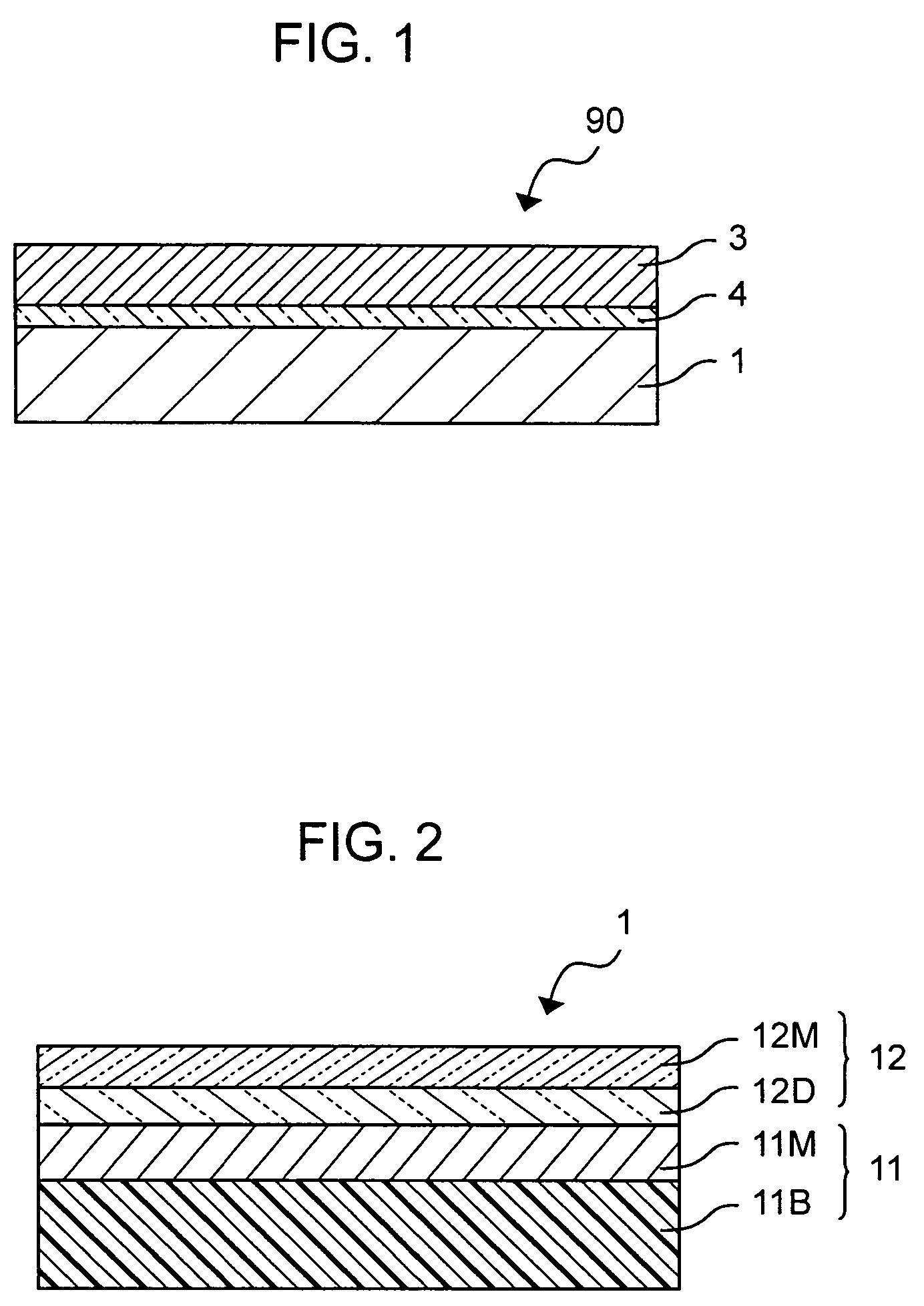
[0097]A reflective sheet 1 shown in FIG. 2 was prepared by sputtering.

[0098](a) Reflective layer 11[0099]Substrate 11B: a PET film (188 μm in thickness)

[0100]Metal film 11M: Al film (50 nm in thickness)

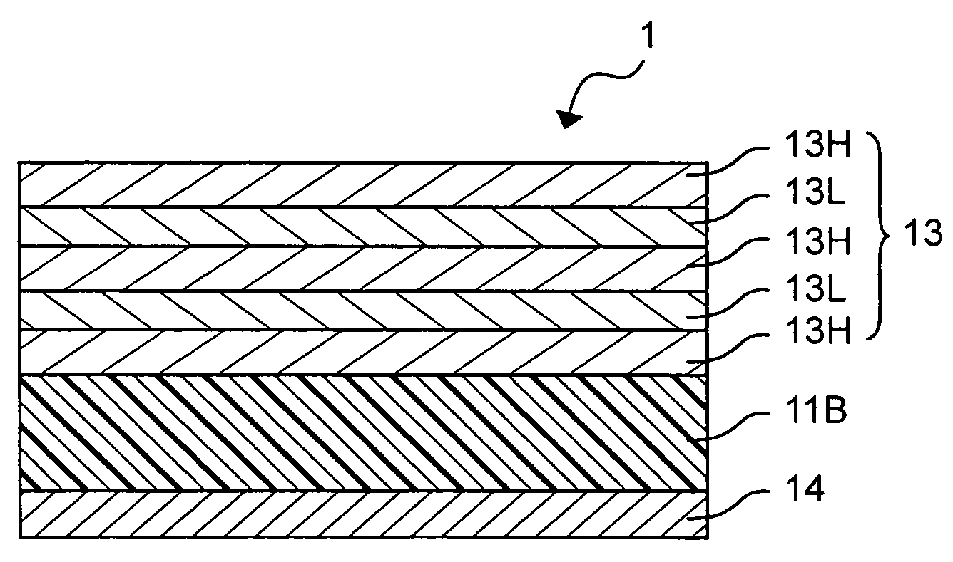
[0101](b) Optical laminate 12: Nb2O5 / Nb / Nb2O5 (thickness: 560 nm / 19 nm / 550 nm (Al layer side))

[0102](2) Adhesive Layer 2

[0103]An acrylic resin was used as the base resin, and a cyanine compound represented by structural formula (A) was used as the coloring material. The content of the coloring material was the same as sample (6) shown in FIG. 8.

[0104](3) Light-Scattering Sheet 3

[0105]An epoxy resin layer was formed on a PET film, and by using a master die carrying a surface texture prepared in advance, irregularities were transferred onto the epoxy resin layer.

[0106]The resulting light-scattering sheet 3 was bonded onto the surface of the reflective sheet 1 ...


PUM

PropertyMeasurementUnit
reflectanceaaaaaaaaaa
refractive indexaaaaaaaaaa

Abstract

A reflective screen is provided. A reflective screen that displays an image by reflecting light from a light source includes a reflective sheet, a light-scattering sheet, and an adhesive layer bonding the reflective sheet to the light-scattering sheet. The adhesive layer contains a coloring material that absorbs light in a particular wavelength region.

Description

CROSS REFERENCES TO RELATED APPLICATIONS[0001]The present application claims priority to Japanese Patent Application JP 2004-178007 filed in the Japanese Patent Office on Jun. 16, 2004, the entire contents of which are incorporated herein by reference.BACKGROUND[0002]The present invention relates to reflective screens. In particular, it relates to a wavelength-selective reflective screen onto which an image from a projector, such as a video projector, a film projector, or an overhead projector, is projected with excellent color reproducibility and a high contrast even in a bright environment.[0003]Recent years have seen widespread use of overhead and slide projectors by presenters delivering their materials in conferences and the like. Liquid crystal video projectors and motion picture film projectors for home use are also gaining popularity. These projectors operate by optically modulating light emitted from a light source using, for example, a liquid crystal panel, to form imaging...

Claims


Application Information

Patent Timeline
Patent Type & Authority Patents(United States)
IPC IPC(8): G03B21/56G03B21/60G02B5/02G02B5/08G02B5/26G02B27/00G02F1/1335
CPCG03B21/60G02B5/26
Inventor OSHIMA, YOSHIHIROKAKINUMA, MASAYASUCHUBACHI, HIDEYAHAYASHI, HIROSHISHIMODA, KAZUHITOKIRITA, SHINA
Owner SONY CORP
Why Eureka
Try Eureka