
Method and apparatus for controlling temporary traffic signals

a technology for temporary traffic signals and control devices, applied in identification means, ways, constructions, etc., can solve problems such as significant safety issues affecting vehicle operators and passengers, affecting the use of permanent signals, and affecting the safety of drivers

Inactive Publication Date: 2008-09-09
VANGUARD SIGNAL COMPANY
View PDF10 Cites 14 Cited by
  • Summary
  • Abstract
  • Description
  • Claims
  • Application Information

AI Technical Summary

Benefits of technology

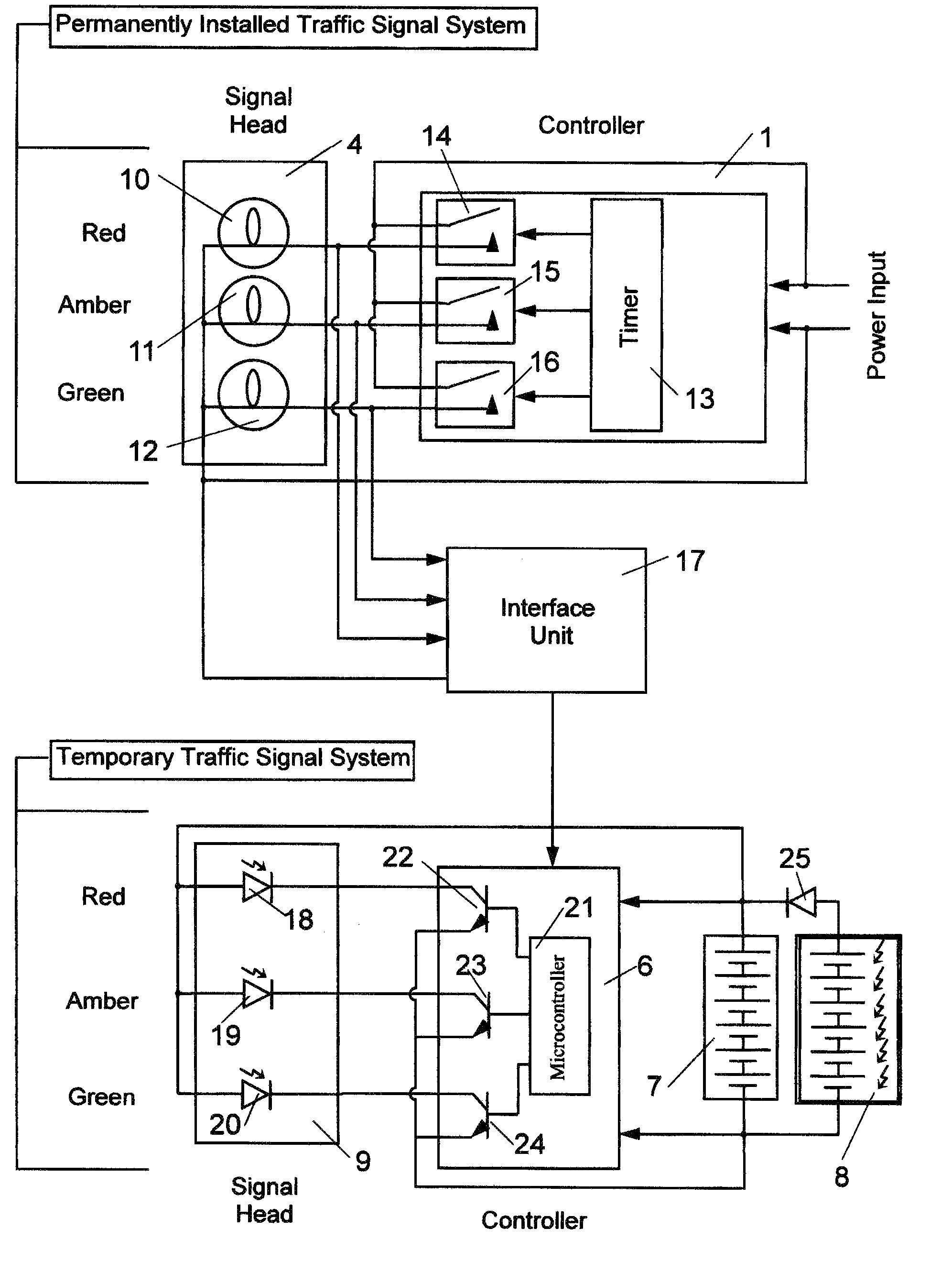
[0007]Another objective of the present invention is to provide a temporary traffic control signal system that may be synchronized in a programmable way or selectable way with a permanent traffic control signal that may be present at the same location.
[0010]When the external control data is present, then the portable system controller may be configured to respond to receipt of the external control data in at least one of a first mode of operation or a second mode of operation. In the first mode of operation, the portable electrically operated signals may be partially or fully inhibited. In the second mode of operation, operation of the portable electrically operated signals may be synchronized with the permanently mounted electrically operated signals to avoid conflicting signals being given by the two systems.

Problems solved by technology

In the event of a power interruption, these signals become inoperative, creating a hazardous situation for vehicle operators and passengers.
However, a significant safety issue hampers their use.
When power is restored to the system, timing of the temporary, portable devices does not match that of the permanently mounted signals.
Even small differences in timing, over a period of minutes or hours, can result in conflicts where, for example, the permanent signal may be red in a given direction, while the portable signal shows green.
It is easy to imagine the confusion this could cause, and the resulting accidents.
Given the typical disruption that results when the power goes out, it could be hours or even days before a crew arrives to remove the portable signal.

Method used


Image

  • Method and apparatus for controlling temporary traffic signals
  • Method and apparatus for controlling temporary traffic signals
  • Method and apparatus for controlling temporary traffic signals

Examples


Embodiment Construction

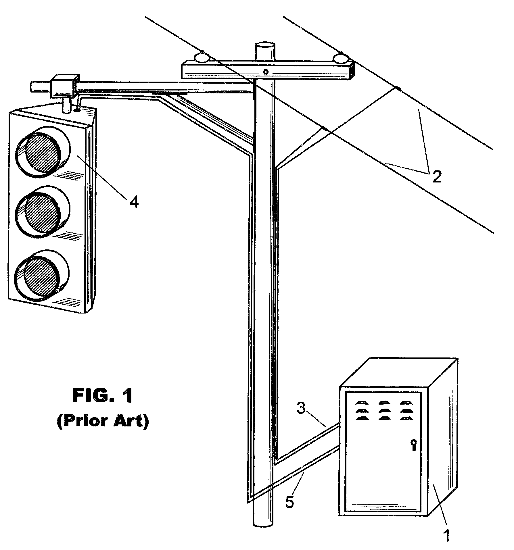
[0028]Now referring to the drawings, and more particularly to FIG. 1, there is shown a typical permanently installed traffic signal that utilizes one or more signal heads 4, connected via a cable 5 to a controller 1. Controller 1 is normally connected by a cable 3 to ac utility lines 2. By permanently-installed it is meant a system that is intended to be continuing or enduring (as in the same state, status, place) without fundamental or marked change for the reasonably foreseeable future and not subject to fluctuation or alteration due to anticipated hazards or outages such as hurricanes, snow storms, or other temporary conditions.

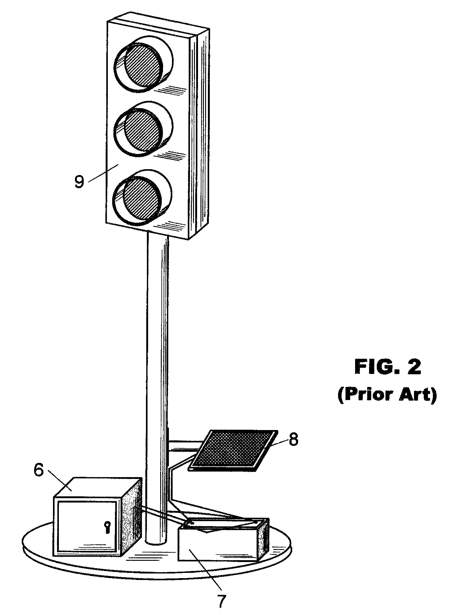
[0029]In FIG. 2, a typical prior art portable traffic signal is shown that consists of one or more signal heads 9, wired to a control unit, 6. Power is typically supplied by a battery pack 7, which may be recharged by a solar panel 8. A temporary system is intended to be lasting for a time only, e.g. existing or continuing for a limited time and is not int...


PUM


Abstract

A temporary or portable traffic signal can be utilized to regulate traffic during power outages. However, when power is restored and the normal operation of the permanently installed traffic signal resumes, then a method of interconnecting the permanent and temporary systems ensures that the operation of the two system are synchronized in predetermined and / or selectable modes of operation. Whenever power is available, an interface detects operation of the permanently installed main system and produces signals that can be used in one mode of operation to direct the portable system to ignore its internal timing sequences and synchronize with the main system, or in another mode of operation to cease its operation.

Description

FIELD OF THE INVENTION[0001]The present invention relates generally to the field of traffic control devices, and particularly to traffic signals intended for portable or temporary use.BACKGROUND OF THE INVENTION[0002]Traffic signals are installed at more than 312,500 intersections in the U.S. These signals are operated by connection to utility power lines. In the event of a power interruption, these signals become inoperative, creating a hazardous situation for vehicle operators and passengers. To alleviate this situation, an increasing number of major intersections have been equipped with backup power systems, typically capable of powering the signals for a few hours, while power is being restored, or temporary stop signs are erected.[0003]A number of portable traffic signals have been designed, which might have use in such situations. However, a significant safety issue hampers their use. When power is restored to the system, timing of the temporary, portable devices does not matc...

Claims


Application Information

Patent Timeline
Patent Type & Authority Patents(United States)
IPC IPC(8): G08G1/095
CPCG08G1/095
Inventor SHARROW, JOHN A.
Owner VANGUARD SIGNAL COMPANY
Learn More