
Systems and methods for electrically connecting circuit board based electronic devices

Inactive Publication Date: 2008-05-01
ICI NETWORKS
View PDF6 Cites 52 Cited by
  • Summary
  • Abstract
  • Description
  • Claims
  • Application Information

AI Technical Summary

Benefits of technology

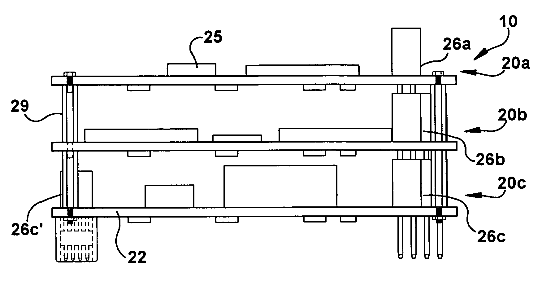
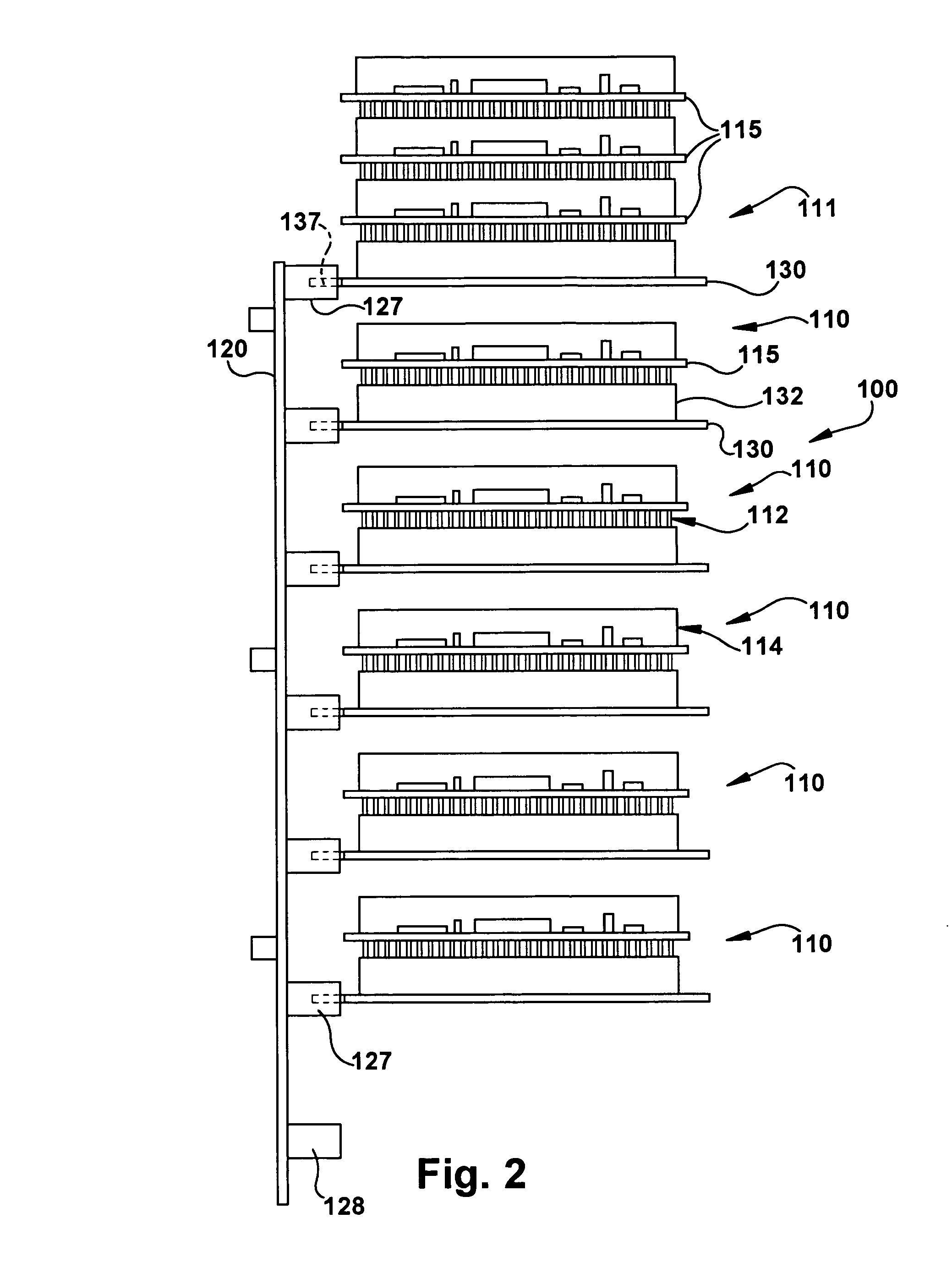
[0007]According to one inventive aspect of the present application, a system may include a power backplane provided to supply modular power connectors for a plurality of modular devices. By providing a separate power connector for each modular device, the system may be configured to allow removal of any one or more of the modular devices from the system without requiring physical removal and / or network interruption of any or all of the remaining devices, as is the case with a conventional self-stacking configuration.
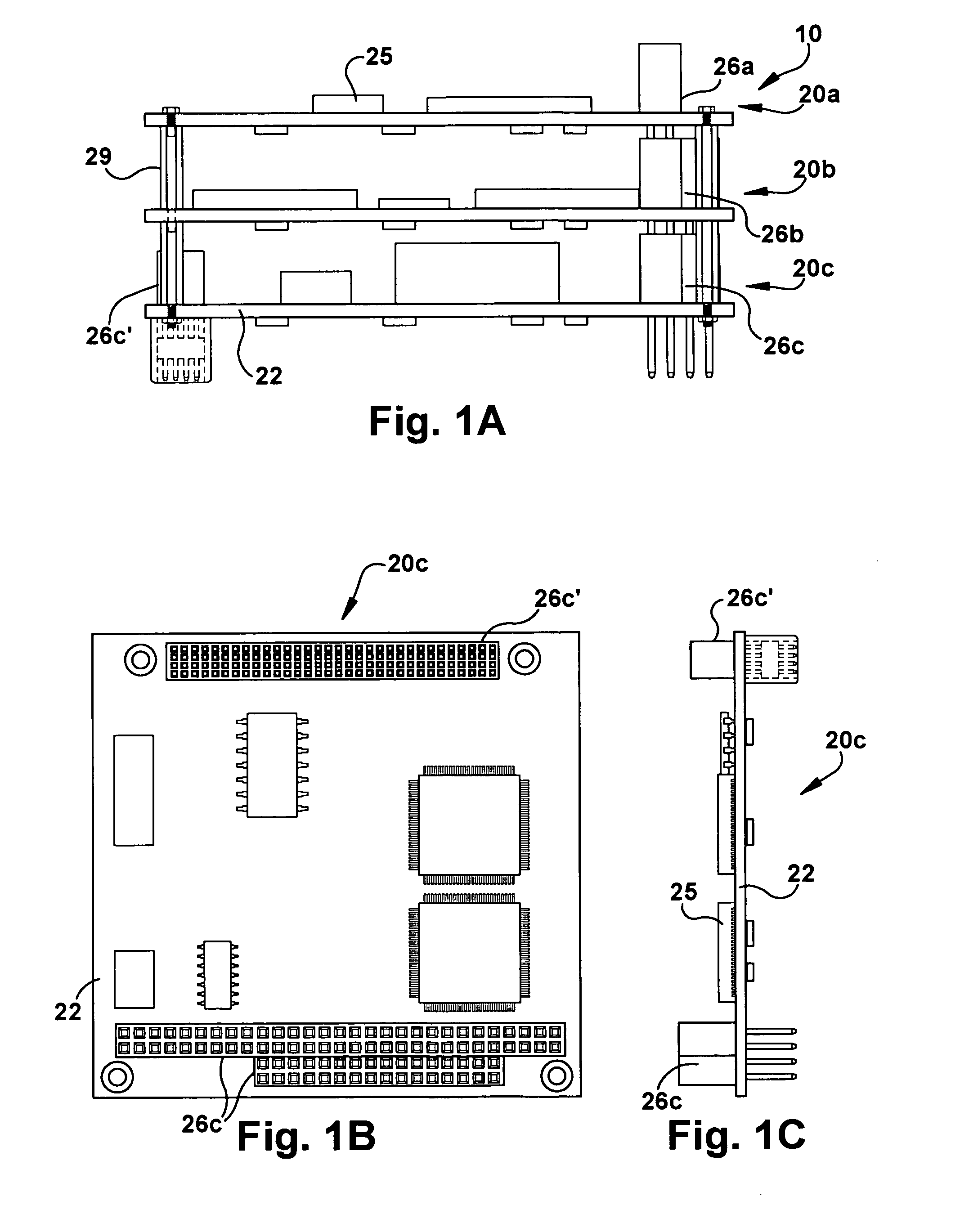
[0008]According to another inventive aspect of the present application, a system may include a plurality of modular devices, with each modular device including a circuit board having electrical contacts connected to an interface portion. The interface portions of the devices may be indirectly connected with each other, using, for example, cables or other such connections. By providing modular devices that are not directly connected with each other, the system may be configured to allow removal or installation of any one or more of the modular devices, such as for repair, replacement, or new installation, from the system without requiring physical removal and / or network interruption of any or all of the remaining devices, as is the case with a conventional self-stacking modular configuration. Also, by limiting data signal interconnectivity between devices in a system, signal conflicts, such as between incompatible devices, may be avoided.

Problems solved by technology

Due to the large number of hardware manufacturers, software developers, and service providers, this interconnectivity may be challenging or even prohibitive when assembling a data communications system.
While the self-stacking arrangement and limited external connectivity of the stack may make construction of such systems easier and more efficient, the manufacturer “bundling” of these modules may present difficulties with regard to end user modifications and servicing of any one or more of the modules.
This may result in extended system downtime, maintenance hazards (particularly for systems in hazardous locations, such as utility poles), risk of improper reassembly, damage during disassembly / reassembly, diagnostic issues, and other difficulties.
Even maintenance on an end-most module on a stack may require removal of the entire stack, due to space constraints within the enclosure that houses the stack.
Further, even if maintenance of a module does not require removal of the stack, a network interruption of one or more of the remaining module devices may be necessary due to the data signal interconnectivity of all of the modules in the stack.
This data signal interconnectivity may also result in potential bus signal conflicts between module devices in the stack, which may limit a user's options in adapting the assembly by replacing or adding electronic devices on the stack.

Method used


Image

  • Systems and methods for electrically connecting circuit board based electronic devices
  • Systems and methods for electrically connecting circuit board based electronic devices
  • Systems and methods for electrically connecting circuit board based electronic devices

Examples


Embodiment Construction

[0020]This Detailed Description of the Invention merely describes preferred embodiments of the invention and is not intended to limit the scope of the claims in any way. Indeed, the invention as described is broader than and unlimited by the preferred embodiments, and the terms used have their full ordinary meaning.

[0021]The present application relates to arrangements for providing electrical connectivity to multiple electronic devices. According to one inventive aspect, a power backplane is used to provide separate modular power connectors for each of the electronic devices in the system. While some embodiments may include a backplane providing both power connectivity and data signal connectivity to the multiple electronic devices, in one embodiment, power connectivity alone may be provided through the backplane, with data signal connectivity being provided by some other means, such as, for example, external cable connections between the modular devices. In one example of such an e...


PUM


Abstract

In one exemplary embodiment, a system for supplying electrical connectivity to one or more circuit board based devices includes a backplane and at least one module. The backplane includes a mounting surface having a plurality of modular power connectors. The at least one module includes an interface portion, a power connection portion, and a circuit board. The power connection portion is configured to connect with the corresponding one of the plurality of modular power connectors. The circuit board includes a plurality of power-related electrical contacts and a plurality of data-related electrical contacts. At least one of the plurality of power-related electrical contacts is connected with the power connection portion, and at least one of the plurality of data-related electrical contacts is connected with the interface portion. The backplane is configured to connect with a power supply, such that the power supply supplies power to the at least one module through one of the modular power connectors when the at least one module is connected with the corresponding modular power connector.

Description

FIELD OF THE INVENTION[0001]The present invention relates to a system for electrically connecting circuit board based electronic devices.BACKGROUND OF THE INVENTION[0002]With advancement in computer-based technologies, such as data communications (including wireless communication), the interconnectivity of multiple electronic devices in data communications systems has become a priority for the manufacturers and users of these system components. Devices such as, for example, PCs, video cameras, radio transmitters, and modems are required to work together, with the help of various adapters, processors, routers, and interfaces, for the efficient and effective operation of the data communications system. Due to the large number of hardware manufacturers, software developers, and service providers, this interconnectivity may be challenging or even prohibitive when assembling a data communications system.[0003]In an effort to provide a compact, powerful, and adaptable format for PC-compat...

Claims


Application Information

Patent Timeline
IPC IPC(8): H01R12/16
CPCG06F1/18H05K1/14H05K1/144H05K2201/10189H05K2201/045H05K2201/049H05K2201/044
Inventor CASTO, BRIAN W.RETTERER, JOHN J.SMITH, THOMAS L.
Owner ICI NETWORKS
Learn More