
Treatment of fluids with wave energy from a carbon arc

a technology of carbon arc and treatment fluid, which is applied in the nature of treatment water, vortex flow apparatus, separation process, etc., can solve the problems of carbon arc lights not being used today for industrial and residential lighting, pollution, and many waterways, and achieves superior wave energy delivery, effective treatment of fluid, and the effect of stripping and destroying volatiles

Active Publication Date: 2008-09-09
FORET PLASMA LABS
View PDF56 Cites 86 Cited by
  • Summary
  • Abstract
  • Description
  • Claims
  • Application Information

AI Technical Summary

Benefits of technology

"The present invention provides a device and method for effectively treating fluids by subjecting them to multiple forms of wave energy simultaneously. This overcomes the problem of absorbance or path length of wave energy through the fluid. The device can be easily installed into existing structures and is superior to prior methods in terms of focus, intensity, and residence time. The method also overcomes the problem of residence time and absorbance phenomena associated with photochemical reactions. The technical effects of the invention include improved wave energy delivery, enhanced stripping and destroying of volatiles, and synergistic treatment of fluids with several forms of wave energy."

Problems solved by technology

Although the industrial revolution has brought about the luxuries and simplicities of life, there has been a world-wide downside - pollution.
Nowadays, it is common to find many waterways, drinking water sources, air and soils contaminated with pollutants.
However, in general carbon arc lights are not utilized today for industrial and residential lighting, as searchlights or for photochemical reaction type applications.
Although there are many methods and devices known in the art, their applications are specific and limited.
Likewise, a PCO device designed for air disinfection has significant drawbacks when an attempt is made to utilize that technology in a liquid environment.
There are a number of major obstacles which have not been overcome by the prior art.
One major obstacle is residence time versus absorbance.
The result of the failure of the prior art to overcome this obstacle is perceived by the end-user (customer) as a problem of “not having enough lights,” of“light penetration,” and / or of “excessive energy requirements (inefficient)”.
However, the changes still do not overcome the problem of residence time versus absorbance.
Any UV system incorporating a “bulb” is prone to burn out.
Consequently, dosages as specified within the '803 patent may not be sufficient to inactivate cryptosporidium.

Method used


Image

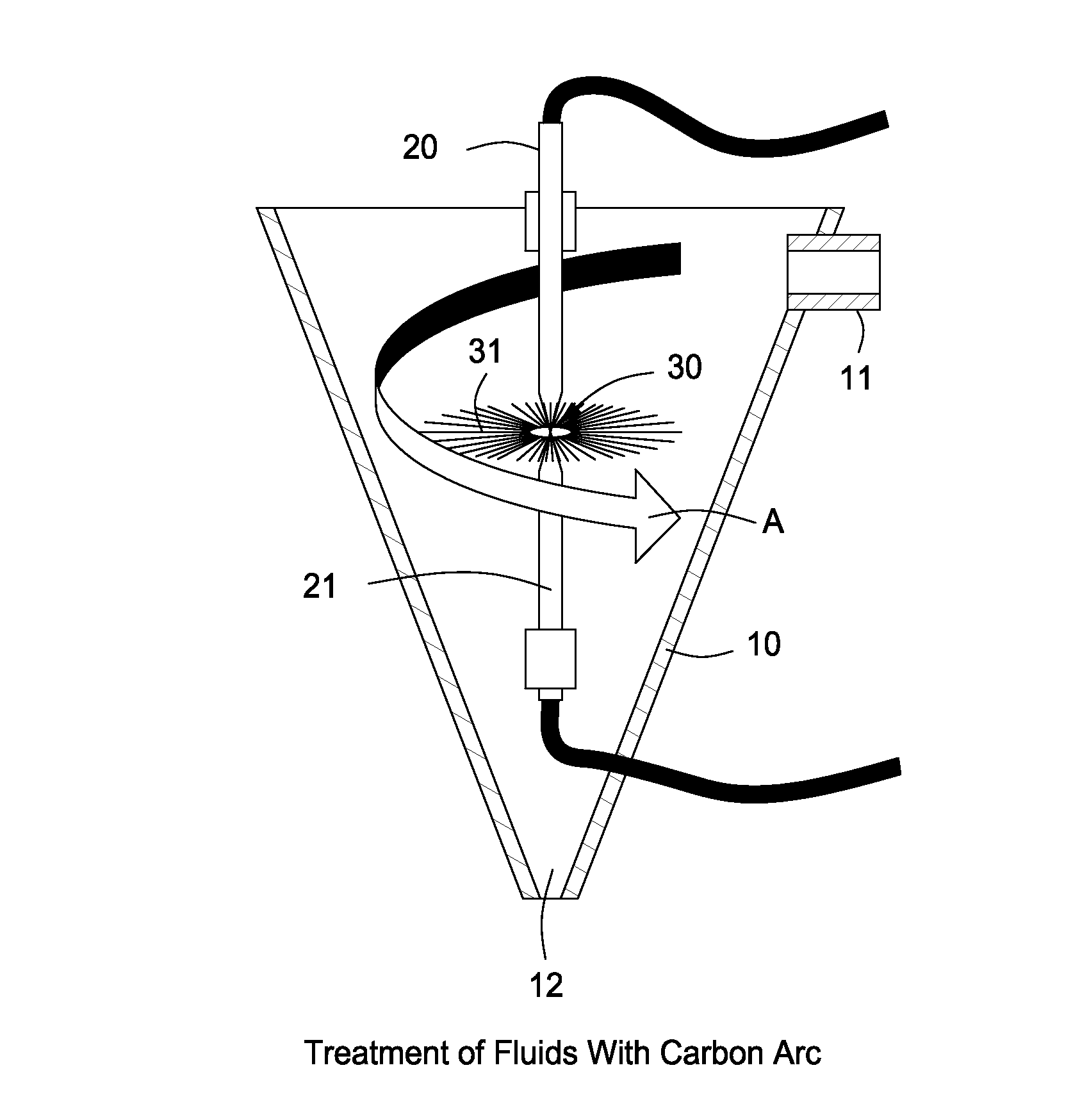
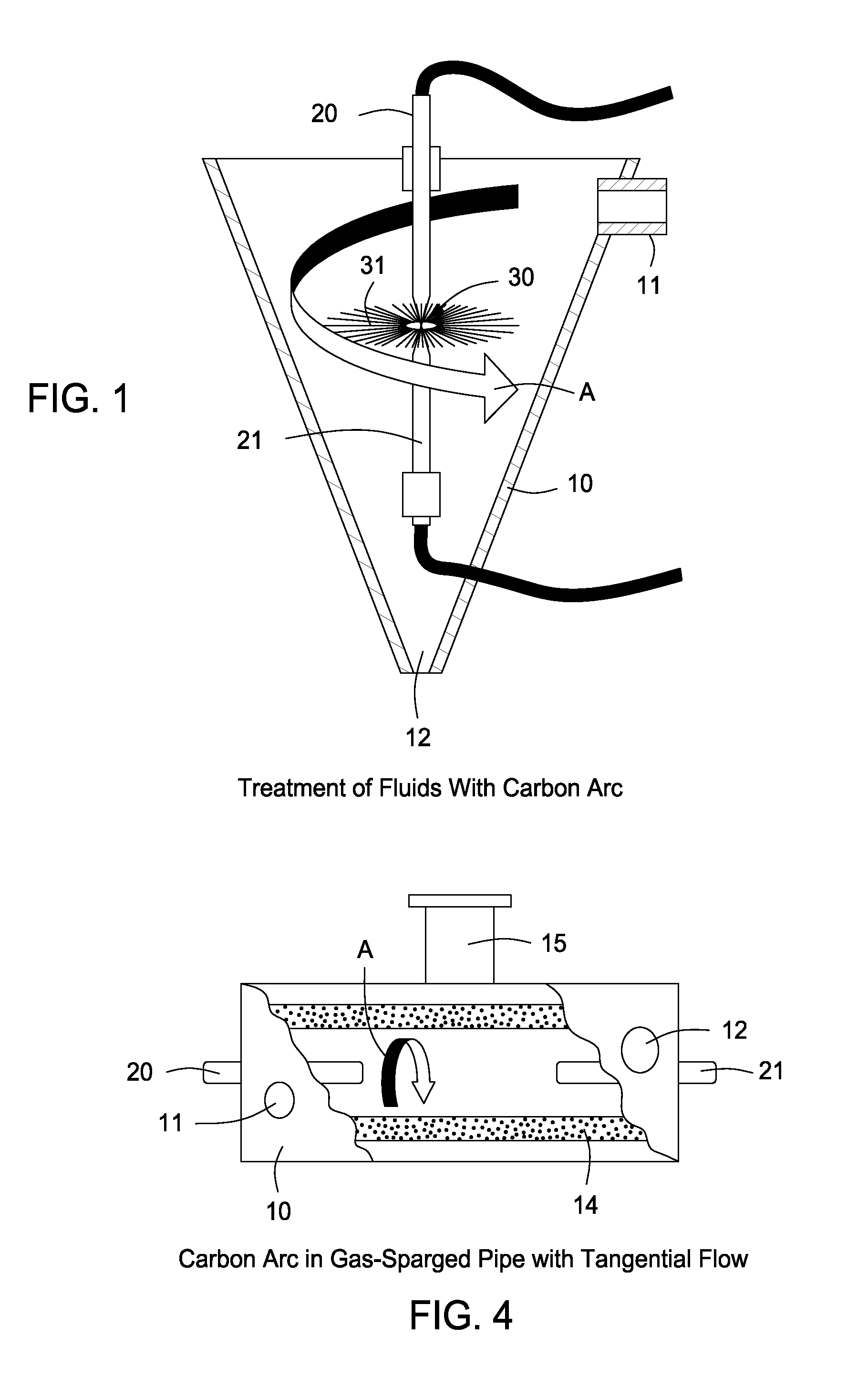
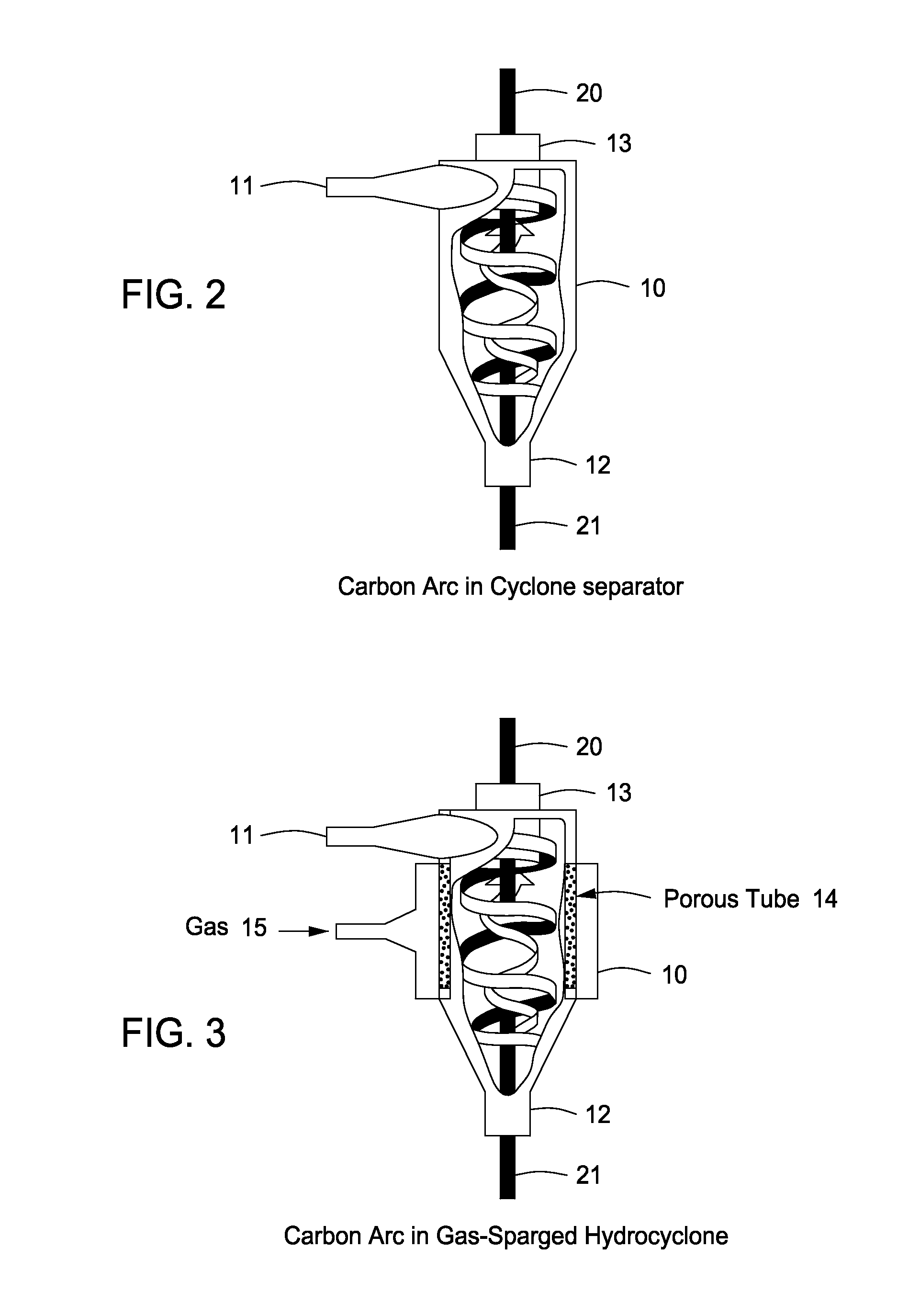
  • Treatment of fluids with wave energy from a carbon arc
  • Treatment of fluids with wave energy from a carbon arc
  • Treatment of fluids with wave energy from a carbon arc

Examples


Embodiment Construction

[0034]Prior art wave energy, in particular EMR, devices and methods, are designed for a given flow rate range. Simply put, the photochemical reactor has a known volume, and based upon the volume of the reactor the number of EMR sources which are needed to effect a reaction over a specified time period is calculated and commonly referred to as residence time (RT). Normally the EMR sources are continuous wave sources such as long linear low-pressure mercury arc lamps, medium pressure mercury lamps and short-arc HgXe lamps. Since these lamps are rated in watts, then the joules / second emitted from the lamps can be multiplied by the RT to specify an effective dose (watts / second / volume) to the treated fluid.

[0035]For example, the amount of radiation necessary to deactivate bacteria is known. Thus, simply by working backwards from this known value, in combination with the average population density of the bacteria, the variable or number of EMR sources and size of the reactor may be easily...


PUM

PropertyMeasurementUnit
light penetration depthaaaaaaaaaa
distanceaaaaaaaaaa
distanceaaaaaaaaaa

Abstract

A method of and apparatus for treating liquids flowing in a thin film around a source of wave energy to directly expose the liquid to the wave energy, preferably generated in whole or part by an electrical arc between carbon electrodes. In addition to the wave energy generated by the electrical arc, energy generated by cavitation of the flowing liquid may be used in treating the liquid.

Description

RELATED APPLICATION DATA[0001]This application claims the benefit of U.S. Provisional Patent Application Ser. No. 60 / 500,445, filed Sep. 5, 2003.FIELD OF THE INVENTION[0002]The present invention generally relates to devices and methods used to treat fluids with wave energy, and in its preferred embodiments more particularly relates to the treatment of fluids with wave energy generated by a carbon arc.BACKGROUND OF THE INVENTION[0003]The term “wave energy” is used herein to include radiation as well as wave energies transmitted by various mediums, and embraces electromagnetic waves or radiations; sonic, supersonic, and ultrasonic waves; neutrons, protons, deuteron, and other corpuscular radiations. The term “electromagnetic waves” includes, e.g., X-ray, gamma-ray, ultraviolet, infra red, and visible light rays, and short electric and radio waves. These definitions and terms are consistent with those used by the U.S. Patent and Trademark Office for classification purposes.[0004]Electr...

Claims


Application Information

Patent Timeline
Patent Type & Authority Patents(United States)
IPC IPC(8): C02F1/32
CPCC02F1/36C02F1/4608C02F1/46109C02F1/48H05B11/00C02F1/30C02F1/32C02F2001/46133C02F2103/008C02F2301/024C02F2301/026C02F2103/22Y02W10/37
Inventor FORET, TODD
Owner FORET PLASMA LABS
Learn More