Power unit for conveyance and conveyance provided with the power unit
a power unit and power unit technology, applied in the field of power units and conveyances, can solve the problems of unnecessary charging of stand-by power sources, and achieve the effect of simple structur
- Summary
- Abstract
- Description
- Claims
- Application Information
AI Technical Summary
Benefits of technology
Problems solved by technology
Method used
Image
Examples
first embodiment
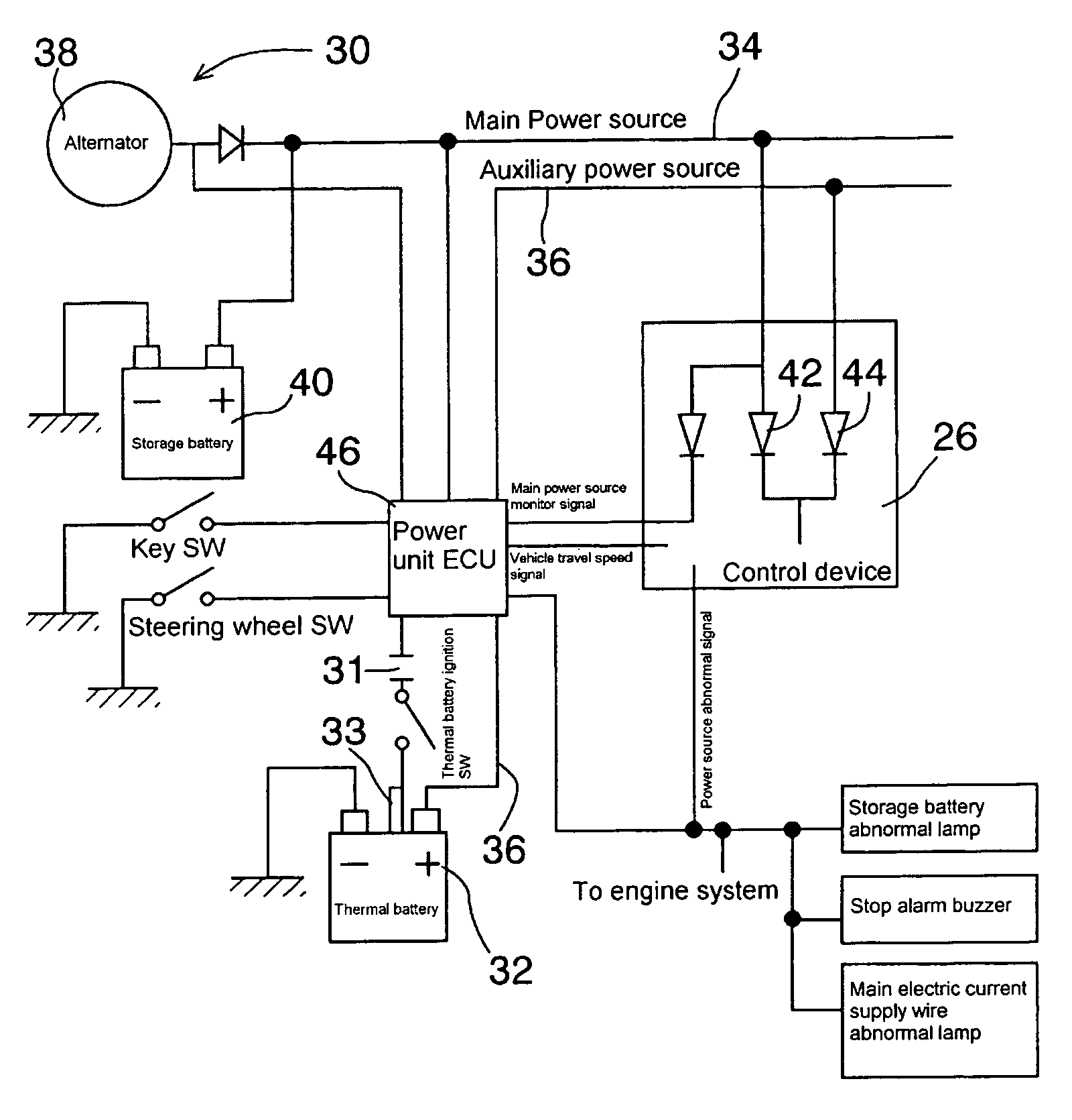
[0091]FIG. 5 shows one example of a structure of a thermal battery employed in the present invention. In the same figure, a positive electrode 94, an electrolyte 95, a negative electrode 96 and a heat generating agent 93 correspond to one cell, and they are laminated to obtain a prescribed voltage. A cell group, together with a thermal insulation material 97 and a squib 91 are inserted and held, and sealed in a metal container 98. When current is carried to a terminal for ignition 90 led out to the outside of the metal container 98, the squib fires, the heat generating agent 93 starts combustion and a temperature of the inside of the thermal battery increases. This heat melts the electrolyte 95, which allows electric power to be taken out from the output terminal 89 through a current collector 92.
[0092]A thermal battery is a reserve battery (battery which can be stored for a long period and can be used immediately when needed) which employs an “inorganic salt electrolyte which is a ...
second embodiment
[0118]There is shown a first preferable structure to solve the problem 1 referring to the accompanying drawings.
[0119]FIG. 6 is a structural diagram showing a first example of a power unit of this structure. A generator 10 and a main storage battery 11, which are the main power sources, are connected to diodes 13, 14 through an ignition switch 12 in the forward direction respectively. When the ignition switch 12 (first switch means) is turned ON (turning to a closed contact), electric current flowing through one diode 13 charges a backup condenser 15 which is a backup power source. The charged backup condenser 15 never discharges by the operation of the diode 13 even when a voltage of the generator 10 and / or the main storage battery 11 decreases. This current discharged from the backup condenser 15 is supplied to a thermal battery activation device 17 through a normally open switch 16 which is a second switch means. At the same time, electric current from the generator 10 and / or the...
third embodiment
[0145]There is shown a second preferable structure to solve the problem 1 referring to the accompanying drawings.
[0146]FIG. 13 is a view showing one example of a circuit of a thermal battery squib ignition device of this structure. This circuit is provided with a main storage battery 1 and an ignition switch 2 which are serially connected and a backup condenser 3 which is parallelly connected. The backup condenser 3 is charged by the main storage battery 1 by operating the ignition switch 2 (closing a contact).
[0147]A constant current circuit A is connected to a power source unit which is provided with the main storage battery 1, the ignition switch 2 and the backup condenser 3 (energy storage means), a prescribed constant current generated in the constant current circuit A flows to a thermal battery squib ignition part 5 for igniting a squib 5a of a thermal battery for stand-by power source. It is to be noted that reference numeral 4 denotes a voltage detection switch (first switch...
PUM
| Property | Measurement | Unit |
|---|---|---|
| voltage | aaaaa | aaaaa |
| saturation voltage | aaaaa | aaaaa |
| voltage | aaaaa | aaaaa |
Abstract
Description
Claims
Application Information
 - R&D
- Intellectual Property
- Life Sciences
- Materials
- Tech Scout
- Unparalleled Data Quality
- Higher Quality Content
- 60% Fewer Hallucinations
Browse by: Latest US Patents, China's latest patents, Technical Efficacy Thesaurus, Application Domain, Technology Topic, Popular Technical Reports.
© 2025 PatSnap. All rights reserved.Legal|Privacy policy|Modern Slavery Act Transparency Statement|Sitemap|About US| Contact US: help@patsnap.com


