
Photomask with reduced electrostatic discharge defects

a technology of electrostatic discharge and photomask, applied in the field of photolithography, can solve the problems of no longer generating the desired optical pattern of the photomask, damage to the glass plate and/or the patterned metal layer, and so as to reduce the prevent electrostatic discharge related defects, and high surface area differential

Active Publication Date: 2008-09-02
INTEGRATED DEVICE TECH INC
View PDF10 Cites 20 Cited by
  • Summary
  • Abstract
  • Description
  • Claims
  • Application Information

AI Technical Summary

Benefits of technology

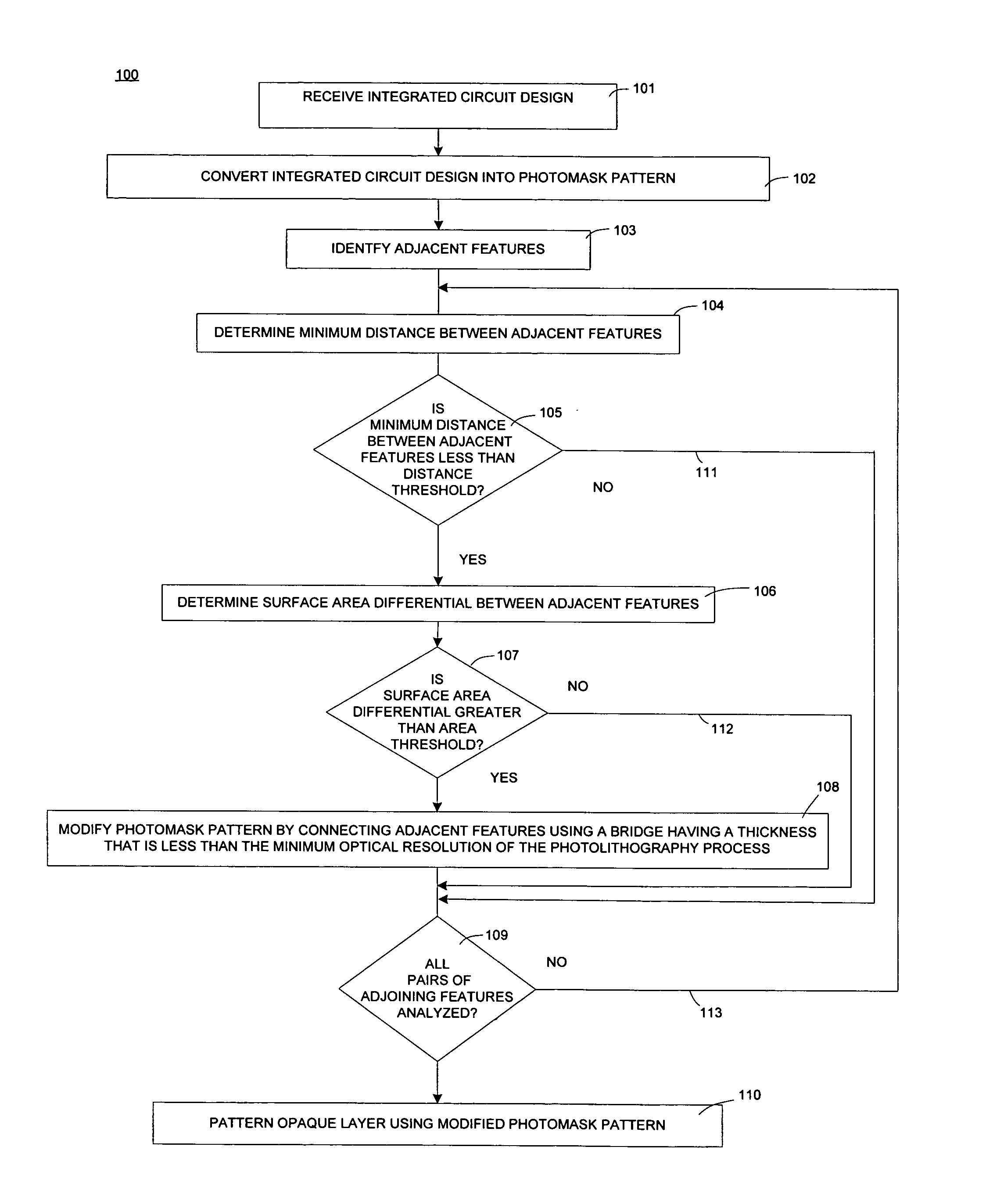
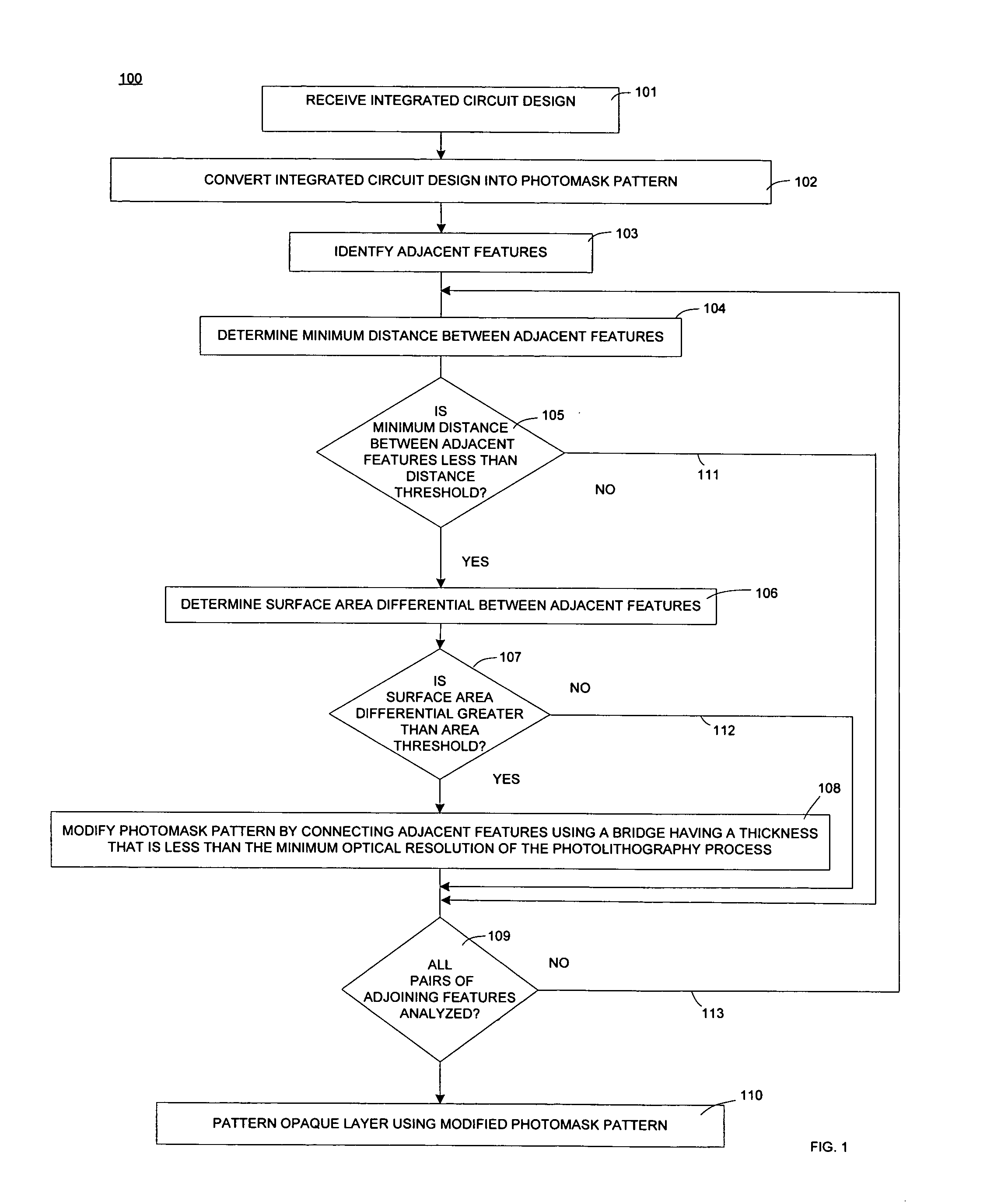
The present invention provides a method for making a photomask that reduces electrostatic discharge related defects. This is done by modifying the pattern of the photomask to connect features that are likely to produce such defects using a bridge that has a width less than the minimum optical resolution of the photolithography process. The result is a photomask that includes bridges that connect structures that are likely to produce electrostatic discharge related defects, reducing the number of such defects.

Problems solved by technology

Charge imbalances between the structures on the photomask can lead to electrostatic discharge related defects.
More particularly, electrical charge can move between adjacent structures, resulting in damage to the glass plate and / or damage to the patterned metal layer.
This damage to the photomask can alter the optical characteristics of the photomask such that the photomask no longer generates the desired optical pattern.

Method used


Image

  • Photomask with reduced electrostatic discharge defects
  • Photomask with reduced electrostatic discharge defects
  • Photomask with reduced electrostatic discharge defects

Examples


Embodiment Construction

[0017]Reference will now be made in detail to the preferred embodiments of the invention, examples of which are illustrated in the accompanying drawings. While the invention will be described in conjunction with the preferred embodiments, it will be understood that they are not intended to limit the invention to these embodiments. On the contrary, the invention is intended to cover alternatives, modifications and equivalents, which may be included within the spirit and scope of the invention as defined by the appended claims. Furthermore, in the following detailed description of the present invention, numerous specific details are set forth in order to provide a thorough understanding of the present invention. However, it will be obvious to one of ordinary skill in the art that the present invention may be practiced without these specific details. In other instances, well-known methods, procedures, components, and circuits have not been described in detail so as riot to unnecessaril...


PUM

PropertyMeasurementUnit
widthaaaaaaaaaa
distanceaaaaaaaaaa
areaaaaaaaaaaa

Abstract

A photomask and a method for forming a photomask are disclosed in which the photomask pattern is modified to bridge features that are likely to produce electrostatic discharge related defects. In one embodiment those adjacent features that are closely spaced together and have a high surface area differential, are bridged using a bridge that has a width less than the minimum optical resolution of the photolithography process.

Description

FIELD OF THE INVENTION[0001]The present invention relates to the field of photolithography. More specifically, the present invention relates to a photomask and a method for forming a photomask having reduced electrostatic discharge defects.BACKGROUND ART[0002]Photomasks are used in semiconductor manufacturing processes to transfer patterns onto semiconductor wafers and other substrates. In conventional semiconductor manufacturing processes an integrated circuit design is submitted to a photomask manufacturer in electronic form. The photomask manufacturer converts the integrated circuit design into a photomask pattern that is stored in a pattern data file. This photomask pattern is then transferred to an opaque layer of a photomask to form a photomask that includes a non-opaque substrate and a patterned opaque layer.[0003]One type of photomask, typically referred to as a reticle, is designed for use in a stepper or scanner. The stepper or scanner generates coherent light that passes ...

Claims


Application Information

Patent Timeline
Patent Type & Authority Patents(United States)
IPC IPC(8): G03F1/00
CPCG03F1/144G03F7/70433G03F1/40
Inventor AHN, JAE-GYUNG
Owner INTEGRATED DEVICE TECH INC
Learn More