
Stable attachment microphone stand systems

a microphone stand and bracket technology, applied in the direction of mouthpiece/microphone attachment, piezoelectric/electrostrictive transducer, transducer type, etc., can solve the problems of loosening the attachment, time-consuming and potentially destructive assembly and disassembly of the microphone pole to its base, and failure of traditional microphone stands, etc., to achieve the effect of quick assembly and disassembly of the microphone stand

Active Publication Date: 2008-08-12
A C T LIGHTING INC +1
View PDF10 Cites 26 Cited by
  • Summary
  • Abstract
  • Description
  • Claims
  • Application Information

AI Technical Summary

Benefits of technology

[0013]It is another object of the present invention to provide smooth mating of a longitudinal axial element into a support base.
[0014]It is yet another object of the invention to provide a quick assembly and disassembly of a microphone stand.

Problems solved by technology

Traditional microphone stands may have been unsuccessful possibly due to a failure to provide a sufficiently stable and quick attaching microphone stand.
The assembly and disassembly of a microphone pole to its base may be time consuming and potentially destructive, possibly due to cross-threading.
This movement may loosen the attachment and may even allow a pole to undesirably detach from a base during use.
Yet, this may have resulted in a time consuming and frustrating disassembly and assembly.
Threading features of microphone stand systems may have been difficult to properly align the parts, such as from a standing position with a base resting on the floor, and many revolutions of a pole or shaft may be have been required for full tightening.

Method used


Image

  • Stable attachment microphone stand systems
  • Stable attachment microphone stand systems
  • Stable attachment microphone stand systems

Examples


Embodiment Construction

[0026]As mentioned earlier, the present invention includes a variety of aspects, which may be combined in different ways. The following descriptions are provided to list elements and describe some of the embodiments of the present invention. These elements are listed with initial embodiments, however, it should be understood that they may be combined in any manner and in any number to create additional embodiments. The variously described examples and preferred embodiments should not be construed to limit the present invention to only the explicitly described systems, techniques, and applications. This description should further be understood to support and encompass descriptions and claims of all the various embodiments, systems, techniques, methods, devices, and applications with any number of the disclosed elements, with each element alone, and also with any and all various permutations and combinations of all elements in this or any subsequent application.

[0027]Generally, a micr...


PUM


Abstract

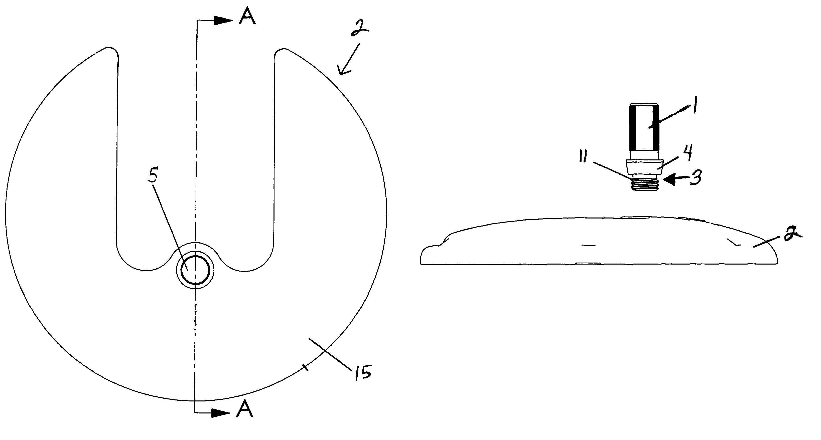
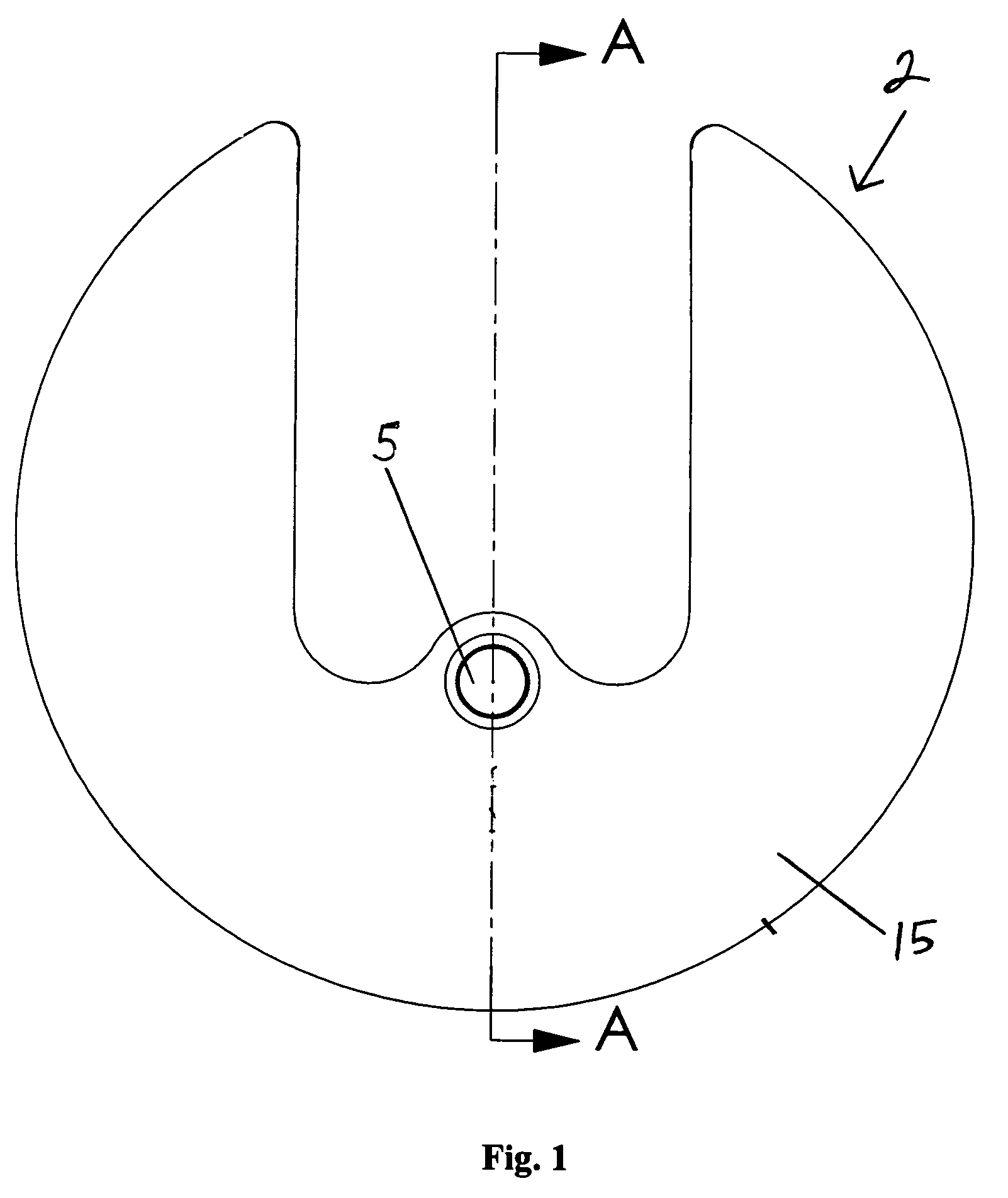
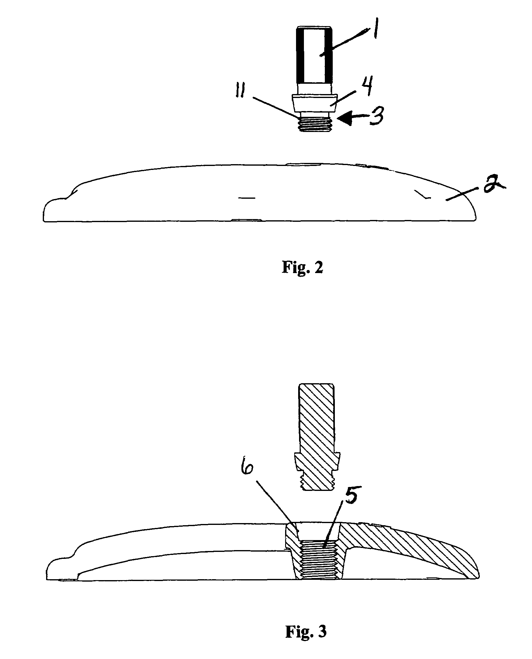
Microphone stand attachment systems to attach a support base to a longitudinal axial element easily, quickly and securely. An attachment guide may include a threaded plug and a support base may include a threaded socket. In embodiments, a male tapered flange may frictionally lock with a female tapered element of a socket to secure a longitudinal axial element to a support base. Specific attachment structures, in embodiments, are also described, as are various plugs, tapers, sockets and methods of attaching a support base to a longitudinal axial element.

Description

BACKGROUND[0001]This invention relates to microphone stand systems that may facilitate microphone stand assembly and disassembly and may even stabilize an assembled microphone stand. The invention may provide, in general, a microphone stand assembly that has a longitudinal axial element securely attached, yet removable from a support base.[0002]Under some circumstances, it may be desirable for a microphone stand to be easily disassembled and assembled to facilitate transportation. Traditional microphone stands may have been unsuccessful possibly due to a failure to provide a sufficiently stable and quick attaching microphone stand. Microphone stand assemblies may include a threaded microphone pole attached to a weighted base which may be attached by threading the pole into the base. The assembly and disassembly of a microphone pole to its base may be time consuming and potentially destructive, possibly due to cross-threading. When attached, a pole may not be stably situated into the...

Claims


Application Information

Patent Timeline
Patent Type & Authority Patents(United States)
IPC IPC(8): H04R25/00
CPCH04R1/08
Inventor WORKMAN, JONATHAN P.EIMEN, TODD
Owner A C T LIGHTING INC
Learn More